background image

- 12 -

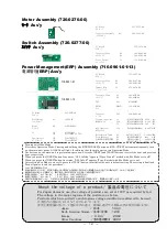
Motor Assembly (726-0276-00)

Ass'y

PC Board

115-2675-00

PC ボード

Connector Assembly

K1

309-2283-04

コネクタAss'y

Switch Assembly (726-0277-00)

Ass'y

PC Board

115-2676-00

PCボート

Connector Plug

K1

308-0206-00

コネクタプラグ

K2

308-0508-00

Lever Switch

S1

356-0102-00

レバースイッチ

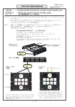
About the voltage of a product/ 製品 の 電 圧に つ い て

For Japan domestic use, the voltage of products are set at 100V as required by law

The voltage in the major regions of the world are as below.

Products which are suited to each regions voltage condition are allowed to be used.

日本国内の電圧は100Vと定められています。
世界主要地域の例として電圧は次の通り、地域に適合する製品以外は使用出来ません。

Japan

/ 日本

:100V

North America・Taiwan / 北米・台湾

:120V

Europe

/ ヨーロッパ

:230V

Other Countries

/その他の国々 :220V

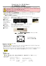
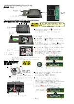
エコモードON/OFF切替え方法
初めに操作モードに入る、 OPEN/CLOSEとSA-CD/CDボタンを同時に押しながら電源を入れると全てのLEDが点灯、入ったことを表す。
操作は本体のボタンキーを使用する。NEXT(進む)/BACK(戻る)ボタンを押して項目を選びます。
NEXTを6回押し ”ALL InIt du”

( D,Uタイプ向け、エコモードはOFFになる)

NEXTを7回押し ”ALL InIt E ”

( E タイプ 向け、エコモードはONになる)

ON/OFFの設定が決まったら、PLAYボタンを押し設定が確定し出荷状態に初期化します。電源を切り終了します。

Turning on/off Eco Mode

First enter Operation Mode. Pressing and holding the [OPEN/CLOSE] button and [SA-CD/CD] button simultaneously, turn

on the main unit power. All LEDs will light. It indicates that the main unit enters Operation Mode.

Use buttons on the main unit to perform an operation. Press the [NEXT] and [BACK] buttons to select the next and previous

item, respectively.

When you press the [NEXT] button four times, "ALL InIt du" appears (Types D and U models with Eco Mode set to off).

When you press the [NEXT] button five times, "ALL InIt E" appears (Type E model with Eco Mode set to on).

After setting Eco Mode to on or off, press the [PLAY] button to initialize the unit to default setting. The setting is finalized.

Turn off power to end the procedure.

Power Management(ERP) Assembly (716-0961-01/13)

電源管理

(ERP) Ass'y

PC Board

115-2227-20

PCボート

Connector Plug

K1

308-0327-00

コネクタプラグ

K2

308-0206-00

Jumper Wire

J1

678-0070-00

ジャンパーリード

PC Board

115-2227-20

PCボート

Zener Diode

D1

UDZV6.2B

ツェナーダイオード

Diode

D2

S1ZB60-7062

ダイオード

IC

IC1

NJU7231U33

IC4

NJU7700F4-28-TE1

Opt-isolator

IC2

TLP170J/TP/F

オプトアイソレータ

IC3

PC123X2YFZ0F

716-0961-13

Connector Plug

K1

308-0327-00

コネクタプラグ

K2

308-0206-00

FET

Q1,2

RUC002N05

RELAY

RELAY1

362-8101-00

リレィ

Varistor

VS1

420-0001-00

バリスタ

Ceramic Capacitor

C1

CK725B1C226M32TM

22uF / 16V

磁器コンデンサ

C2,4

CK725B1E104K16TM

0.1uF /25V

C3

CK725B1E105K16TM

1uF / 25V

MPP Capacitor

C5,6

CF922MF2E104MR46

0.1uF/250V

MPPコンデンサ

Metal Mixed Thick

R1

RK73K1J112JE-T

1.1kΩ1/10W

Film Resistor

R2

RK73K2H102KETSG

1kΩ

1/2W

金属混合皮膜抵抗器

R3

RK73K1J682JE-T

6.8kΩ1/10W

R4

RK73K1J102JE-T

1kΩ

1/10W

716-0961-01

Summary of Contents for DP-430

Page 1: ...chnical services beyond the instructions herein provided Following service instructions are prepared only for personnel qualified for technical services Those bearing the specified part number shall a...

Page 2: ...nit is heavy and therefore exercises caution when you perform the work Weight of finished product 14kg 14Kg Precautions for Assembly Tightening torque for screws OPTICL Optical connector fixing screw...

Page 3: ...RTS Push button 5 gang 5 388 5113 03 Binding Screw 4pcs 604 0408 00 Washer 4pcs 637 0042 07 Panel End cap L 132 0132 14 Panel End cap R 132 0133 14 Push button Open Close 388 5115 04 Push button Input...

Page 4: ...5 1 Glass Frame 247 1445 03 6 Indicator 173 9164 03 6 1 Indicator Mounting Bracket 247 1452 03 6 2 Push in Rivet 643 0304 50 7 Position Indicator 173 0907 04 1pce 1pce 1pce 1pce 2pce 2pcs 1 2 3 7 Pin...

Page 5: ...ion plate 159 0113 04 Bridge 112 1435 21 CD Mechanical Assembly CD Ass y 731 0020 00 Power Supply Assembly Ass y 719 0093 00 The part or component having this mark is important to safety Those bearing...

Page 6: ...nt to safety Those bearing the specified part number shall always be used The part or component having this mark is not supplied separately Position Indicator 173 0907 04 Push button Frame 113 0159 02...

Page 7: ...Bottom Plate Binding Screw B Leg Binding Screw B Power Transforer Binding Screw B Owner s Manual ERP Eco Notes USB Utilities Setup Guide USB USB Utility CD USB CD Power Supply Cord J type U T type E...

Page 8: ...134 0159 14 Sub Panel Ass y Ass y 134 0159 14A6 Disc Cushion 3pcs 250 1311 04 Guide Frame 113 0132 03 Bearing 283 0004 04 Spacer 250 0085 04 Bearing 283 0011 03 Spacer 250 1310 04 Bearing 2psc 283 00...

Page 9: ...250 1318 24 Chucking Pulley B B 201 0003 03 Bridge 112 1435 21 Chucking Pulley A A 201 0002 03 Construction for Bridge Decoration Plate 159 0113 04 Magnet 271 0003 00 Oval Head Screw 6pcs 631 0088 00...

Page 10: ...ector of spindle motor Ass y on the back is removed Ass y 6P The flat cable shown in the left figure is connected to the new traverse And please make a style of a flat cable in the mark direction Next...

Page 11: ...citor Display Assembly 723 0250 00 Ass y Transistor Q1 2SC2712 GR Digital Transistor X1 RN1505 Infrared Receiver IC1 RPM7238 H8R IC IC2 TC74VHCT08AF EL Push Switch S1 2 354 1121 00 S3 4 5 6 7 354 1122...

Page 12: ...133 T9B Optical Receiver IC34 PLR135 T9 RELAY RELAY1 5 362 0211 00 Slide Switch S1 350 0207 00 Conductive Bracket SHIELD1 246 0038 04 Crystal Resonator XTAL1 527 0060 00 XTAL3 527 0055 00 Crystal XTAL...

Page 13: ...lect the next and previous item respectively When you press the NEXT button four times ALL InIt du appears Types D and U models with Eco Mode set to off When you press the NEXT button five times ALL I...

Page 14: ...lowing figure 7 CD SACD No DP 430 001 Bridge 112 1435 21 Bottom View Top View Side View Hole for Chucking pulley for CD for SACD The hole by the side of a projection of the object for CD and opposite...

Page 15: ...0066 DAC Ass y K5 K6 K7 723 0250 DISPLAY Ass y T160mA L 250V at 220 240V T315mA L 250V at 100 120V FUSE BRN BLU WHT BLU AC100 120 230V 50 60Hz T1 Attention mark indicating critical components for saf...

Page 16: ...V 11 9V 6 9V 6 9V 3 4 5 6 13 14 15 16 17 18 19 T1 510 4049 10 1 2 1 2 1 2 1 2 DAC Ass y K7 Power switch Ass y K3 Attention mark indicating critical components for safety Replacement must be made with...

Page 17: ...08 1206 00 3 3VD 3 3VD SCAN1 SCAN0 SCLK_BUF EN_DISP_BUF LAT_DISP_BUF SDATA_BUF SCLK SDATA EN_DISP LAT_DISP 47u 6 3V C2 VCC LED_PLAY LED_PAUSE D2 SEL2610C C D 1 2k R5 D3 SEL2610C C D 1 2k R6 SCAN1 SCAN...

Page 18: ...EG_LB SEG_LC SEG_LD SEG_LE SEG_LF SEG_LG DIG_L6 SEG_LH DIG_L6 A 1 F 2 G 3 E 4 D 5 DPK 6 DPA 7 C 8 COM 9 B 10 D1 LAP 301DLTU SEG_LA SEG_LB SEG_LC SEG_LD SEG_LE SEG_LF SEG_LG DIG_L7 SEG_LH DIG_L7 D9 SEL...

Page 19: ...EG_RA SEG_RB SEG_RC SEG_RD SEG_RE SEG_RF SEG_RG DIG_R5 SEG_RH DIG_R5 A 1 F 2 G 3 E 4 D 5 DPK 6 DPA 7 C 8 COM 9 B 10 D1 LAP 301DLTU SEG_RA SEG_RB SEG_RC SEG_RD SEG_RE SEG_RF SEG_RG DIG_R6 SEG_RH DIG_R6...

Page 20: ...SPDIF_TO_RX 47 R213 47 R214 47 R219 47 R215 100 R206 47 R216 11 10 IC27E 47k R261 1 2 K4 308 0242 00 100n C235 SV3 3V SV3 3V 10k R253 10k R252 22p C229 22p C228 47 R257 100 R258 47 R256 D3 3V SHUTDN...

Page 21: ...E CS_DIR SEL1 SEL0 EXT_RST AK_INT SHUTDN EXT_RST MUTE AK_INT CP_INT SEL1 SEL0 CS_DIR PowerOff CS_DIT CS_CP SCLK_UB SDATA CS_DIT CS_CP SCLK_UB SDATA SPI_D2U SPI_D2U SCL SCL SDA SDA SCLK SCLK 100n C124...

Page 22: ...0D R49 47 R74 47 R56 LRCKL DATAR 47 R63 47 R80 47 R64 47 R82 47 R66 47 R73 BCKR MCKR BCKL DATAL LRCKL MCKL BCKR DATAR LRCKR MCKR NC 1 PD 2 BICK DCLK 3 SDATA DSDL 4 LRCK DSDR 5 6 CS 7 CCLK SCL 8 CDTI S...

Page 23: ...1 2 M1 224 0001 00 1 2 K1 309 2283 04 22 MOTOR ASS Y 726 0276 00 SWITCH ASS Y 726 0277 00 1 2 K1 308 0206 00 L C L C 1 2 3 4 5 K2 308 0508 00 L C L C OP_SW CL_SW CL_SW OP_SW 1 2 3 4 5 S1 356 0102 00...

Page 24: ...362 8101 00 1 2 3 4 IC2 TLP170J TP F VS1 420 0001 00 D2 S1ZB60 7062 250V 100n C5 250V 100n C6 16V 22u C1 100n C2 1 1k R1 6 8k R3 1k R4 A 1 K 2 EM 3 CO 4 IC3 PC123X2YFZ0F Attention mark indicating crit...

Page 25: ...sories Case 801 0287 00 Top Board 803 0033 14 Bag 810 0930 04 Battery LR6 3 569 0008 00 Poly Bag for Battery 812 0507 00 Poly Bag for Owner s Manual 812 2435 04 Remote Commander RC 130 729 0130 00 Aud...

Page 26: ......
Page 27: ...Mbps compliant Suitable cable USB 2 0 cable COAXIAL 32kHz to 192kHz 16 to 24 bils 2 channel PCM OPTICAL 32kHz to 96kHz 16 to 24 bits 2 channnel PCM USB 32kHz to 384kHz 16 to 32 bits 2 channnel PCM 2...
Reviews: