■
Supplied accessories:
Notes
●
An FM antenna is required to use the T-1100. Please consult your dealer regarding antenna installation.
●
In residences with shared antenna systems, confirm that the antenna outlet carries FM signals.
●
Use a 75-ohm coaxial cable with F type plug for the antenna connection.
●
The specifications and appearance of this product are subject to change without notice.
I1005Y
PRINTED IN JAPAN
851-0194-00
(
B1
)
Interference signal
400 kHz
300 kHz
200 kHz
Selectivity
70 dB
30 dB
10 dB
*
2
-
(
(
/
4
)
6
0
(
1
Pulse tuning system
Digital output connector
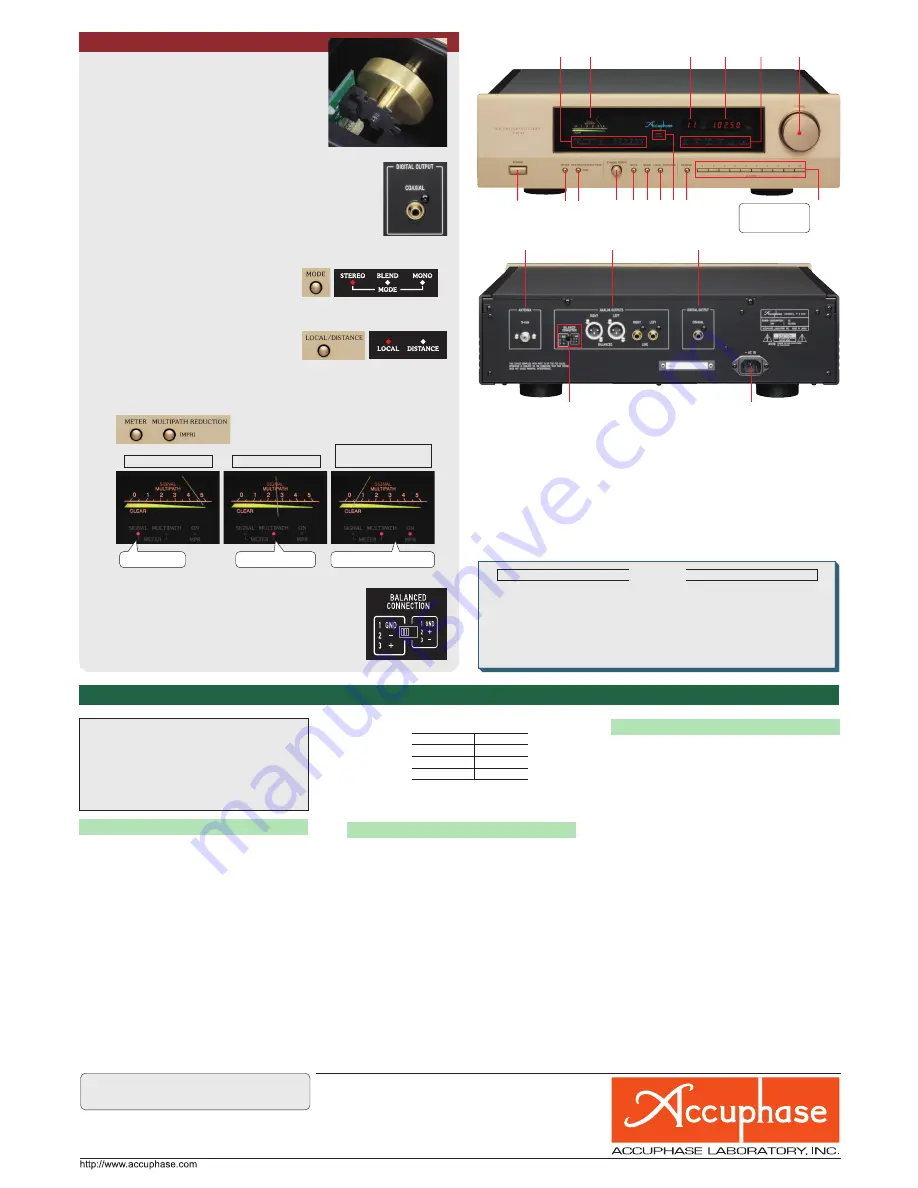
Signal strength indication
Multipath level indication
Multipath reduction
(MPR) ON
SIGNAL indicator lit
MULTIPATH/MPR indicators lit
MULTIPATH indicator lit
Attenuator function
Meter function selection and
MPR ON/OFF switching
MODE button
2 stations can be
programmed
in each button
■
Front panel
■
Rear panel
●
AC power cord
●
Audio cable with plugs (1 m)
●
Remote Commander RC-410
/
LED indicators
METER
MPR
IF BAND WIDTH
4
Meter (Signal strength/Multipath)
)
Station number readout
0
Reception frequency readout
(
1
LED indicators
MUTE MODE
LOCAL
DISTANCE
6
Tuning knob
2
Power switch
*
Meter function button SIGNAL/MULTIPATH
-
Multipath reduction (MPR) ON/OFF button
IF bandwidth selector knob
Muting circuit ON/OFF button
Mode selector button
STEREO / BLEND / MONO
LOCAL/DISTANCE selector button
Stereo reception indicator
Memory set button
Station buttons (20 stations)
Antenna input connector (F type)
(
Phase selector for balanced output
Analog output connectors BALANCED LINE
Digital output connector COAXIAL
AC power connector (for supplied power cord)
(
Monophonic
●
Sensitivity
Usable sensitivity
11 dBf
S/N 50 dB quieting sensitivity
17 dBf
●
S/N ratio
(80 dBf input, A-weighted)
90 dB
●
Total harmonic distortion
(80 dBf input,
±
75 kHz deviation)
20 Hz 0.02 %
1 kHz 0.02 %
10 kHz 0.02 %
●
Intermodulation distortion
(80 dBf input,
±
75 kHz deviation)
0.01
%
●
Frequency response
10−15,000 Hz
+
0 − 2.0 dB
●
Capture ratio
1.5 dB
●
RF intermodulation
80 dB
●
Spurious response rejection
120 dB
●
Image rejection
100 dB
●
Alternate channel selectivity
●
AM suppression
(65 dBf input)
80 dB
●
Output voltage
(
±
75 kHz deviation)
1.0 V
Stereo
●
Sensitivity
S/N 40 dB quieting sensitivity 29 dBf
S/N 50 dB quieting sensitivity 37 dBf
●
S/N ratio
(80 dBf input, A-weighted)
85 dB
●
Total harmonic distortion
(80 dBf input,
±
75 kHz deviation)
20 Hz 0.04
%
1 kHz 0.04
%
10
kHz
0.04
%
●
Intermodulation distortion
(80 dBf input,
±
75 kHz deviation)
0.03
%
●
Frequency response
10
−
15,000 Hz
+
0
−
2.0 dB
●
Stereo separation
100 Hz 60 dB
1 kHz 60 dB
10 kHz 50 dB
●
Stereo trigger level
21 dBf
●
Subcarrier suppression ratio
70 dB
General
●
Antenna input
75-ohm coaxial (F type connector)
●
Standing wave ratio
1.5
●
Tuning principle
DDS synthesizer tuning
20-station random memory tuning
●
FM detection principle
Digital FM demodulation principle
●
Stereo demodulation principle
DS-DC
●
Digital output
(IEC60958)
COAXIAL
:
0.5
V
P-P
75 ohms
Sampling frequency
:
48 kHz/24 bits
●
Output impedance
BALANCED (XLR type connector)
:
100 ohms
(
50 ohms/50 ohms
)
LINE (unbalanced)
:
50
ohms
●
Meter
Signal strength/multipath switchable
●
Power requirements
AC 120 V/230 V, 50/60 Hz
(Voltage as indicated on rear panel)
●
Power consumption
20 W
●
Maximum Dimensions
Width
465 mm (18-5/16")
Height
140 mm (5-1/2")
Depth
406 mm (16-0")
●
Weight
13.0 kg (28.7 lbs) net
19.0 kg (41.9 lbs) in shipping
carton
T-1100 Guaranteed Specifications
[Guaranteed specifications are measured according to EIA standard RS-490.]
(
This product is available in versions for 120/230 V AC. Make sure that the voltage
shown on the rear panel matches the AC line voltage in your area.
(
The shape of the AC inlet and plug of the supplied power cord depends on the
voltage rating and destination country.
(
The reception frequency range, number of display digits, and tuning frequency steps
differ in models for different countries. The antenna connector may also be an IEC
type or F type connector. Please verify that you have the correct model for your area.
Remarks
■
Two sets of analog outputs: balanced and line
■
Phase selector for balanced output
●
In the factory default condition, the switch is set to
the left side (pin 3 positive).
●
If the connected preamplifier or integrated amplifier
uses a “pin 2 positive” arrangement, change the
setting of the switch.
■
20 - s t a t i o n m e m o r y with all function set-
tings
■
Accuphase original pulse tuning system
provides traditional manual tuning feel
■
Confirmation beep when operating tuning
knob and function buttons
■
High-quality digital output connector (coaxial)
■
MUTE button allows turning muting ON or OFF
during tuning
■
MODE button allows selection of desired
reception mode
:
STEREO: Normal stereo reception
@
BLEND: Left and right signals are
mixed, to reduce noise
particularly in the upper
frequency range
.
MONO: Stereo
broadcast
reception forced to
monophonic
■
Attenuator function for reducing input
level
LOCAL: Attenuator ON
■
Meter for monitoring signal status
S
ignal strength as well as multipath condition and effect of multipath
reduction (MPR) can be verified.
Versatile Array of Functions
Frequency range and tuning step width
Model for Europe
87.50 MHz - 108.00 MHz
(in 50-kHz steps)
Model for USA
87.5 MHz - 108.0 MHz
(in 100-kHz steps)


