24
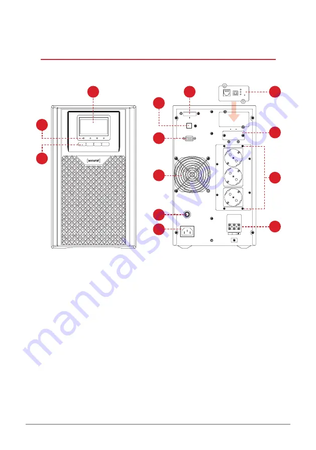
4. Get to know your device
*Note:
This image is for guidance only and may not accurately reflect the product
components shown. During installation, ensure that the plus and minus cables
are connected correctly.
1.
LCD
2.
LED Indicators
3.
Function Buttons
4.
Emergency power off
5.
USB
6.
RS232
7.
Cooling System
8.
Circuit Breaker
9.
AC Input
10.
Extended Battery Connector
11.
AC Output Socket
12.
AC Ring Type Terminal Block
(Only for GUARD 2000)
13.
LOG SNMP Card (OPTIONAL)
default
USB
Ethernet
RS232
INPUT
BREAKER
AC INPUT
AC OUTPU
T
AC OUTPUT
LN
USB
EPO ROO
BAT
INTELLIGENT SLOT
6
7
9
8
5
4
1
10
13
12
11
2
3
S1
S2
S3


