Control Center Components
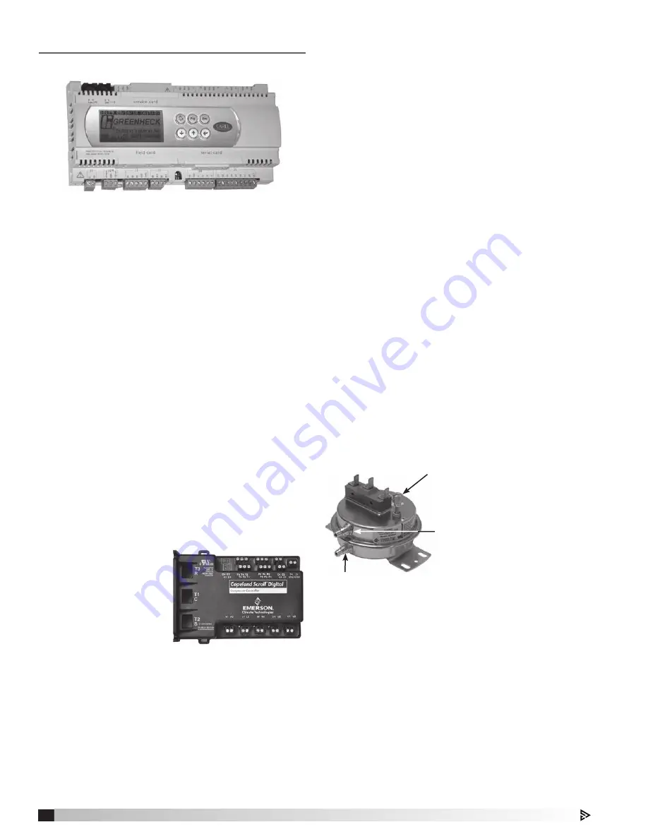
DDC Control Package
Each unit is equipped with a microprocessor controller
commonly called a DDC, located in the main control
center. Depending on settings put in by the user and
the optional sensors ordered with the unit, the DDC
will control the operation of the unit and respond to
changing ambient conditions. The DDC will sense
outdoor air temperature and room temperature
(optional) and then regulate both heating and cooling.
It will switch from heating mode to cooling mode, as
needed. If an optional dehumidistat is ordered, the
DDC will also sense humidity levels in the space and
will adjust operation of the reheat coil during cooling
mode operation. All needed settings for the unit are
entered directly into the controller by means of push
buttons and both settings and operating conditions
can be easily viewed on the large LCD screen. An
optional remote interface panel is also available to
allow set points and other controller settings to be
adjusted from a remote location (see also Optional
Field-Installed Control Sensor. Microprocessor (DDC
Remote Interface. For further information on the
DDC controller, refer to the control catalog and the
Installation, Operation and Maintenance manual
provided with the controller.
Typical DDC Controller
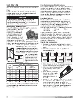
Digital Scroll Compressor Controller
If the optional digital
scroll compressor
was ordered, the
main control center is
also equipped with a
dedicated controller
that monitors and
controls the operation
of the digital scroll
compressor. The
controller has LED
indicator lights to verify
correct operation and also various alarm conditions.
Typical Digital Scroll
Compressor Controller
(optional)
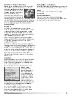
Fan Proving Switch
The unit uses a pressure switch to prove fan operation
before operating any heating or cooling sequence. It
does this by verifying a difference in air pressure on
both sides of the air supply fan. While the operation
of the switch is verified at the factory, the pressure
switch should be adjusted to meet field conditions.
To adjust the switch, the supply fan must be running
with all of the access doors closed in order to
maintain normal operating pressures within the unit.
The control center door may be left open to access
the proving switch (see Proving Switch Location,
Electrical Information / Control Center Components).
The adjusting screw is located on the top of the
switch. Turning the screw clockwise will increase
the amount of pressure difference required to pull
the switch in, and turning it counterclockwise will
decrease the pressure difference required. Adjustment
to the switch is made while viewing the Supply Fan
Status screen on the DDC. Consult the DDC unit
control manual on how to view the Fan Proving
screen. While viewing the Fan Input Proving screen,
adjust the pressure switch so that the fan status
changes from “Open” to “Closed” or from “Closed” to
“Open”. Slightly decrease the set point by turning the
adjustment screw counterclockwise three rotations
to allow for pressure fluctuations and air density
changes. The supply fan alarm may require resetting
before the unit can operate normally.
Note that similar pressure switches may be found as
part of optional devices such as a dirty filter sensor.
Setscrew (on front of switch)
must be manually adjusted after
the system is in operation.
Negative pressure connection
is toward the ‘front or top’ of
the switch.
Senses pressure on
the blower side of filters.
Positive pressure connection is toward the ‘back
or bottom’ of the switch.
Senses pressure at air inlet
side of filters.
12
Model MPX Make-Up Air Unit
Model XMPX Make-Up Air Unit


