


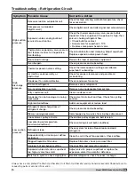
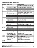


Troubleshooting - Alarms
The first step in troubleshooting the unit is to
check the on-board alarm indicators. Several of the
electronic controls in the unit monitor the system for
faults and will go into alarm, shutting down the unit or
a single function within the unit. All these devices are
discussed further in the Control Center Components
portion of this IOM.
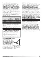
DDC Controller
Check the screen on the DDC for an alarm condition.
If the DDC is in an alarm condition, a message will
show on the DDC screen.
The DDC is located in
the main control center.
If the DDC is in alarm
condition, the Alarm
button will blink red.
Press the Alarm button to see the specific condition
or to reset the DDC. Refer to the DDC IOM for detailed
information on fault codes and see the unit-specific
wiring diagram.
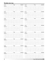
Phase Monitor
The phase monitor has two LED indicator lights, one
red and one green. Green indicates
proper operational status, red
indicates the unit has detected
a fault and is in alarm condition.
The phase monitor is self-resetting
once the alarm condition is
corrected. It is located in the main
control center.
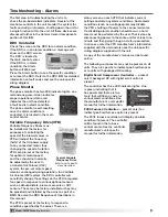
Variable Frequency Drive (VFD)
Variable Frequency Drives may
be installed at the factory for
purposes of controlling the
speed of the blower motors. A
VFD will adjust the frequency
(hertz) of the AC power supply
to any connected motor, thus
changing the speed of rotation.
VFDs are pre-set at the factory
for optimum motor speed
and they should not normally
be adjusted by the user. In
a Constant Air Volume (CAV)
system, the pre-set motor speed
remains unchanged during operation. In a Variable
Air Volume (VAV) system, the DDC controller will
constantly change the settings on the VFD to regulate
fan speed in response to various optional sensors
such as dehumidistats, pressure sensors or CO2
sensors. These may be factory-installed or they may
be provided and installed by the owner as part of a
BMS. See also the DDC Sequence of Operations in
this manual.
The VFD is preset at the factory to respond to
conditions specified by the owner. There is a
The following components may not be present on all
units. They are specific to indirect gas-fired furnaces
or to units with packaged DX cooling.
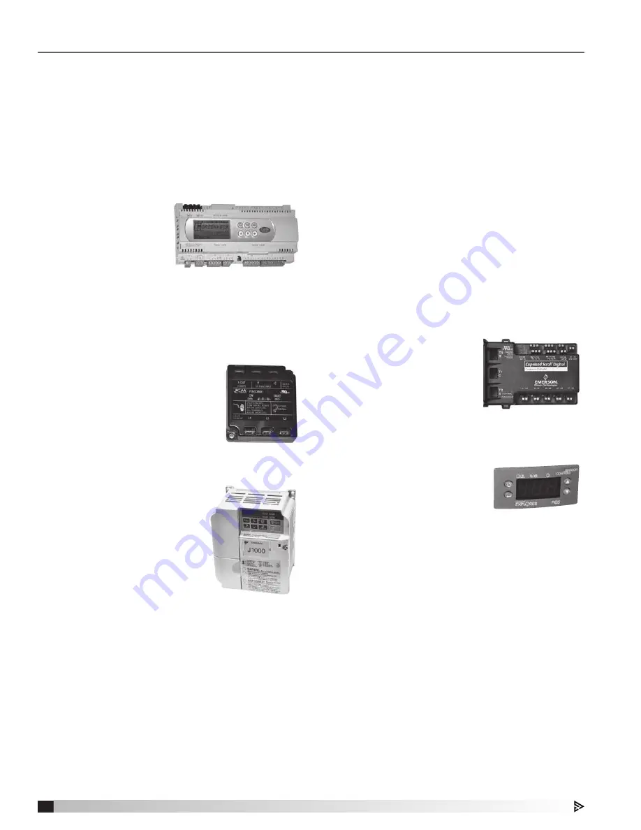
Digital Scroll Compressor Controller
—
present
only if packaged DX with digital scroll option is
present
The controller has three LED indicator lights. One
is green, indicating that it
has power and there are two
more that will flash a code for
various alarm conditions. See
the manufacturer’s unit-specific
manual for further information.
FX05 Furnace Controller
—
present only if an
indirect gas-fired furnace option is present
The FX05 furnace controller will display an alarm
condition if present. The controller
will be found in the furnace
control center. See the controller
manufacturer’s unit-specific
manual for further information.
status screen on each VFD that indicates current
settings and also any alarm conditions. Some alarm
conditions (such as a voltage spike) may disable
the VFD, shutting off power to the connected motor.
If a disabling alarm condition should occur, a hard
reset must be performed by the user. That is done by
disconnecting power to the entire unit for at least one
minute and then going through a start-up procedure.
In all cases, refer the VFD manufacturer’s information
supplied with the unit and also see the unit-specific
wiring diagram supplied with the unit.
A copy of the manufacturer’s manual can be found
online.
Typical Variable
Frequency Drive
(refer to unit-specific
documenation)
28
Model MPX Make-Up Air Unit
Model XMPX Make-Up Air Unit


