background image

Service Clearances

The units require minimum clearances for access on 
all sides for routine maintenance. Filter replacement, 
drain pan inspection and cleaning, fan bearing 
lubrication and belt adjustment are examples of 
routine maintenance that must be performed. Blower 
and motor assemblies, coil and filter sections are 
always provided with a service door or panel for 
proper component access. Clearances for component 
removal may be greater than the service clearances, 
refer to drawings for these dimensions.

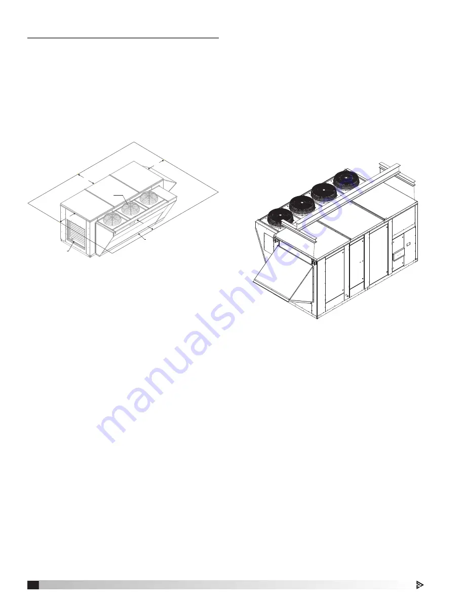
Additional clearances for units with 
Packaged DX

Clearances must be maintained on all sides of 
this model. This especially is true with the top of 
this unit. Hot air is being discharged through the 
condensing fans during operation, and the more 
clearance available, the better the chance of avoiding 
recirculation or coil starvation. This unit should never 
be placed under an overhang or inside a building. A 
minimum of 48 inches over the condensing fans is 
recommended.

Handling Concerns for Units with 
Packaged DX

While this unit was constructed with quality and 
dependability in mind, damage still may occur during 
handling of the unit for installation. Exercise extreme 
caution to prevent any damage from occurring to the 
refrigerant system. This unit contains a system that 
is pressurized with refrigerant and if it is damaged, 
the refrigerant could leak into the atmosphere or 
cause bodily harm due to the extreme cold nature of 
expanding refrigerant. Use protective equipment such 
as gloves and safety glasses to minimize or prevent 
injury in case of a system leak during installation.

IG FURNACE

CONDENSER
FANS

CONDENSING COIL

36 inches

42 inches

42 inches

66 inches

Lifting


1.  Before lifting, be sure that all shipping material 

has been removed from unit.


2.  To assist in determining rigging requirements, 

weights are provided in the Unit Weights & 
Dimensions section on page 5.


3.  Unit must be lifted by all lifting lugs provided at 

the top of the unit.


4.  Rigger to use suitable mating hardware to attach 

to unit lifting lugs.


5.  Spreader bar(s) must span the unit to prevent 

damage to the cabinet by the lift cables.


6.  Always test-lift the unit to check for proper 

balance and rigging before hoisting to desired 
location.


7.  Never lift units by weatherhoods.


8.  Never lift units in windy conditions.


9.  Preparation of curb and roof openings should be 

completed prior to lifting unit to the roof.

  10.  Check to be sure that gasketing has been 

applied to the curb prior to lifting the unit and 
setting on curb.

  11.  Do not use fork lifts for handling unit.

6

Model MPX Make-Up Air Unit

Model XMPX Make-Up Air Unit

Summary of Contents for XMPX Series

Page 1: ...r seismic activity are present If more information is needed contact a licensed professional engineer before moving forward 1 Follow all local electrical and safety codes as well as the National Elect...

Page 2: ...ed to be taken to prevent deterioration of the unit during storage The user assumes responsibility of the unit and accessories during storage The manufacturer will not be responsible for damage during...

Page 3: ...Center Components DDC Control Package 12 Digital Scroll Compressor Controller 12 Fan Proving Switch 12 Variable Frequency Drives VFD 13 Phase Monitor 13 Typical Wiring Diagram 14 15 Controller Sequenc...

Page 4: ...Operation and Maintenance manuals for additional information Plenum and Plug Indirect Gas Fired Furnace Model PVF PCO3 Controller MPX Subassemblies Blower Each unit has just one backward curved blowe...

Page 5: ...ATER 4 INCH FILTERS I H MPX H34 Unit Size Dimensions MPX H14 MPX H24 MPX H34 MPX H34 Furnaces Single Furnace Double Furnace A 54 3 67 2 72 2 76 2 B 86 6 96 7 97 7 97 7 C 34 0 36 4 33 2 33 2 D 48 1 58...

Page 6: ...mage from occurring to the refrigerant system This unit contains a system that is pressurized with refrigerant and if it is damaged the refrigerant could leak into the atmosphere or cause bodily harm...

Page 7: ...be level Shim as required to level 3 Install Ductwork Installation of all ducts should be done in accordance with SMACNA and AMCA guidelines Duct adapter provided to support ducts prior to setting the...

Page 8: ...rovided with the P trap If local and area building codes permit the condensate may be drained from the P trap onto the roof but a drip pad should be provided beneath the outlet If local and area codes...

Page 9: ...o overheat and eventually fail Maximum allowable imbalance is 2 To determine voltage imbalance use recorded voltage measurements in this formula Low Voltage Controller Circuitry Manufacturer recommend...

Page 10: ...e Air Temperature Sensor All units are supplied with a Discharge Air Temperature Sensor that is to be eld installed prior to unit start up The sensor is to be installed at least three duct diameters d...

Page 11: ...use Blocks 10 Step Down Transformers number varies Low Voltage Side 11 DDC Controller 12 Relays 13 Fan Proving Switch Dirty Filter Switch on side wall 14 Low Voltage Terminal Strip 15 Hot Gas Reheat C...

Page 12: ...ch The unit uses a pressure switch to prove fan operation before operating any heating or cooling sequence It does this by verifying a difference in air pressure on both sides of the air supply fan Wh...

Page 13: ...ed sensors and controlling devices such as CO2 sensors dehumidistats or pressure sensors Refer to the VFD manufacturer s information and unit speci c wiring diagram supplied with the unit For addition...

Page 14: ...R R7 21 24 12 FPS NO C 90 NO3 OAI OAD ACC W BL Y PK Y BL W PK BL R 111 112 SUPPLY FAN M MAIN POWER TO UNIT GROUND L1 L2 L3 DB1 DS1 Y Y PM T1 T2 T3 PM C OUT DL1 4 D1 S4 S6 Y 1 2 ST1 O L 95 96 ST1 A2 A...

Page 15: ...RESSOR RELAY CIRCUIT B R7 COMPRESSOR INTERLOCK RELAY CIRCUIT A R8 COMPRESSOR INTERLOCK RELAY CIRCUIT B RBV REHEAT VALVE CONDENSER RH HEAT RELAY RHV REHEAT VALVE HOT GAS REHEAT S1 EXHAUST SWITCH S3 SUP...

Page 16: ...ehumidi cation Sequence The cooling is controlled to maintain the cooling coil set point The dehumidi cation sequence will be locked out when the OA is less than 10 F above the cold coil set point The...

Page 17: ...the proving switch on the supply air blower and displays an alarm in case of blower failure DX Alarm The DDC monitors the refrigerant pressure and shuts off the refrigeration circuit in the case of hi...

Page 18: ...to enable or disable speci c functions of the unit A unit speci c wiring diagram is included with each panel If speci ed by the owner the remote panel may have a Remote Interface factory installed ins...

Page 19: ...Coil M 1 2 3 4 13 5 12 9 11 13 10 8 13 14 7 15 6 Service Valve for Subcooling Gauge High Side Pressure Drop Circuit A Pressure Port for Troubleshooting Valve Service Valve for Superheat and Low Side P...

Page 20: ...le but excessive bubbles may indicate improper charge or a leak in the system A green dot means that moisture is below a safe operation level in the refrigerant while a yellow dot indicates moisture h...

Page 21: ...n system is excessive cycling on and off The digital scroll compressor eliminates excessive cycling by allowing the compressor to continue to run but internal compression is eliminated in brief cycles...

Page 22: ...Once the call for cooling exceeds 70 then the digital scroll will begin running again in conjunction with the xed scroll compressor see below System Start Up During unit start up amperage draw readin...

Page 23: ...l mode during start up Use necessary precautions to avoid injury All data must be collected while the unit is running In order to measure volts and amps the control center door must be open and the un...

Page 24: ...e Yes No If bubbles are visible in sight glass stop the start up process Refrigerant charge may not be adequate Consult factory Color of Center Dot Green Yellow Hot Gas Bypass Operational Yes No Not p...

Page 25: ...which may cause personal injury or failure of the following components Fan Shaft Bearings Motor Fan Wheel Belt Tighten all fasteners and set screws securely and realign drive pulleys after adjustment...

Page 26: ...cess doors open or without proper ductwork in place as the fan motors will overload Vibration Excessive vibration may be experienced during initial start up Left unchecked excessive vibration can caus...

Page 27: ...low prior to contacting the factory please determine the following information Air ow problems can often be tied back to improper ductwork installation Be sure to install ductwork in accordance with S...

Page 28: ...FD to regulate fan speed in response to various optional sensors such as dehumidistats pressure sensors or CO2 sensors These may be factory installed or they may be provided and installed by the owner...

Page 29: ...t Check motor wiring Check motor nameplate versus supplied voltage Motor horsepower too low See speci cations and catalog for fan curves to determine if horsepower is suf cient Shorted windings in mot...

Page 30: ...a 1 64 inch de ection per foot of span between sheaves Worn belt Replace Motor base or blower loose Tighten mounting bolts Bearing and drive misaligned Realign Noise being transmitted by duct Make sur...

Page 31: ...ine voltage Check line voltage If more than 10 from compressor marking correcting is necessary Compressor motor protector open Motor thermal protector automatically resets Allow time 2 hours for compr...

Page 32: ...erload If compressor is hot allow compressor to cool for two hours Recheck for open circuit Improper refrigerant charge Check subcooling Improperly wired Review wiring schematics Loose wiring Check al...

Page 33: ...ove non condensable from system Dirty condenser coil Clean condenser coil Condenser fan not running or running backwards Check electrical circuit and fuse Check fan cycling controls High load conditio...

Page 34: ...n oversized Contact factory Compressor loses oil Refrigerant leak Check system for leaks Repair leaks and add refrigerant Short cycling Check low pressure control settings Refrigerant ood back Check t...

Page 35: ...air ow Check air ow check lters check drive for loose parts or belts Malfunctioning or defective expansion valve Check bulb of thermal expansion valve Frost on evaporator coil Hot gas bypass valve not...

Page 36: ...ess panels and unit components can be heavy and serious injury may occur This unit requires minimal maintenance to operate properly To ensure proper operation and longevity the following items should...

Page 37: ...ted and require no further lubrication under normal use Normal use being considered 20 F to 120 F and in a relatively clean environment Some bearings are relubricatable and will need to be re greased...

Page 38: ...less may be used to clean coils with a n thickness over 0 0095 inches thick TEST THE SPRAY PRESSURE over a small corner of the coil to determine if the ns will withstand the spray pressure For coils...

Page 39: ...____________________________ _________________________________________________ Date __________________ Time _____________ AM PM Notes ___________________________________________ ______________________...

Page 40: ...transportation prepaid Motors are warranted by the motor manufacturer for a period of one year Should motors furnished by Accurex prove defective during this period they should be returned to the nea...

Reviews: