Fire Ready Hood
26
Fire Alarm Sequence
A fire alarm sequence will only occur upon the detection
of extremely high hood temperatures (approximately
216°), or when the remote pull station is pulled (if
provided).
The fire alarm sequence causes:
1. Audible alarm
2. Fire system (wet chemical) discharge
3. Fuel shut off to disconnect fuel to the cooking
appliance (if not already shut off due to a high
temperature alarm).
After Actuation
1. Shut off power to range (via building breaker).
2. Clean up all wet chemical using soap and warm
water with a sponge. Do not use vacuum cleaner.
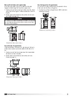
3. Carefully drop the hood into the service position,
remove the fire suppression control board enclosure
cover, and remove the battery from the fire
suppression control board.
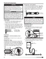
4. Disconnect the tank cylinder release valve terminal
wire connections from the fire suppression control
board.
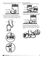
5. Remove the extinguisher cylinder assembly from the
enclosure based by loosening the cylinder band.
6. Unscrew and remove the extinguisher cylinder
manifold / siphon tube assembly from the
extinguisher cylinder. Pour out any leftover wet
chemical in the cylinder.
7. Refill extinguisher cylinder with 4.9 lbs. of wet
chemical agent (part of recharge kit).
NOTE
The fire alarm sequence can only occur when the fire
suppression control board is running in fire detect
mode.
NOTE
To mute the audible alarm, place the hood into
service position, and press “RESET” button on fire
suppression control board.
NOTE
A complete system inspection and servicing must be
done immediately following a kitchen range top fire.
Consult an authorized fire equipment company for
service or proper procedure.
NOTE
All service on the fire suppression system after
actuation should be performed by authorized
equipment distributor.
CAUTION
Before replacing the wet chemical, the tank, release
valve assembly, it is recommended to wear approved
type of eye protection and rubber gloves.
8. Flush out existing distribution assembly water to
remove residual wet chemical and blow dry.
9. Replace the extinguisher cylinder manifold O-ring
and reinstall manifold / siphon tube assembly into the
extinguisher cylinder (part of recharge kit).
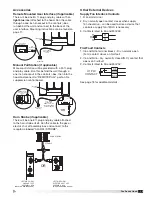
10. Connect a nitrogen supply line to the ¼ inch male
quick connect fitting and pressurize to 100 PSI.
11. Reinstall the extinguisher cylinder assembly in the
enclosure base.
12. Refer to the “Arming the System” section on page
18
to reactivate the system.
CAUTION
Do not use extinguisher cylinder gauge to determine
when the intended charge pressure has been reached.
AVERTISSEMENT
Ne pas utiliser le manomètre du cylindre extincteur
pour déterminer le moment où a été atteint la pression
de charge prévue.
NOTE
Upon performing the fire system diagnostic test,
additional components may need to be replaced as
a result of the high temperatures and flames that
occurred during the fire. Replace these parts as
necessary (see “Parts” on page 29).

