background image

Fire Ready Hood

5

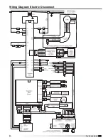
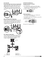
Wiring Diagram: Electric Disconnect

Summary of Contents for XRRS Series

Page 1: ...n Kitchen Fire Safety Tips published by NFPA General Safety Information Personnel should have a clear understanding of these instructions and all applicable current local and national building and fire codes before installing this product AVERTISSEMENT Pour réduire le risque d incendie de choc électrique ou de blessure corporelle respecter ce qui suit Utiliser uniquement ce produit de la façon pré...

Page 2: ...se User Interface optional Recessed Mount J Box One 1 81 2 ft Plug and Play Cable Manual Pull Station optional One 1 30 ft Plug and Play Cable Horn Strobe optional One 1 8 ft Plug and Play Cable Wall Cap optional K Class Portable Fire Extinguisher optional Fire Test Kit optional Additional Spare Fuses Qty 1 4A Fuse and Qty 1 6A Fuse Handling Handle hood and accessories in such a manner as to keep ...

Page 3: ...LS HOOD CONTROLS PLC RELAYS AND TERMINAL BLOCKS FIRE SUPPRESSION DROPS WITH NOZZLES QTY 2 MODEL SERIAL INFORMATION STICKER Table of Contents Receiving Unpacking Parts Checklist Handling and Storage 2 Model Number Code 3 Hood Exploded View 3 Ventilation and Fan Type Configurations 4 Installation General Information and Hood Weights 7 Dimensional Data and Mounting Bracket 8 Ductwork 9 Hood 9 Externa...

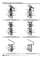
Page 4: ...tchen Cabinets Soffit External Inline Fan provided Roof Cap by others 10 in Ductwork by others 12 in to 10 in Transition by others 10 in to 12 in Transition by others 10 in Ductwork by others Range Hood provided Airflow Kitchen Cabinets Soffit 500 CFM External Inline Fan provided Roof Cap by others 12 in Ductwork by others 12 in Ductwork by others Airflow Kitchen Cabinets Soffit Range Hood provide...

Page 5: ...Fire Ready Hood 5 Wiring Diagram Electric Disconnect ...

Page 6: ...Fire Ready Hood 6 Wiring Diagram Gas Disconnect ...

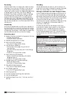
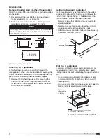
Page 7: ...e with the rear discharge duct After drywall is hung affix mounting bracket to wall using the necessary field provided fasteners through the critical mounting points Minimum Spacing 24 inches Maximum Spacing 30 inches Measure vertical distance from bottom of hood to cooking surface Measure vertical distance from bottom of hood to cooking surface Hood to Cooking Surface Spacing Recommendation WARNI...

Page 8: ...EAR DISCHARGE FAN DUCT 30 Inch Integral Fan Rear Discharge 36 Inch Integral Fan Rear Discharge B A A A A E B C A A E B D D A C A A A A E A A E D D A A A 30 External Fan Top Discharge 36 External Fan Top Discharge MOUNTING BRACKET KEY A CRITICAL MOUNTING POINTS MUST BE SEC OR DRY WALL HANGERS B UTILIZE ONE OF THESE TWO CRITICAL POIN TO STUD OR DRY WALL HANGERS THREE T C LOCATION FOR FACTORY PROVIDE...

Page 9: ...harge Fan by Others 250 10 in round diameter External fan by others should be sized based on hood and duct static pressure Yes Integral Fan Rear Discharge Not applicable 500 5 x 12 in 2 ft Yes External Fan Top Discharge Inline 500 12 in round diameter 35 ft Yes External Fan Top Discharge Fan by Others 500 12 in round diameter External fan by others should be sized based on hood and duct static pre...

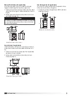
Page 10: ...00 9 38 3 75 5 32 3 75 ELECTRIC SHUT OFF ASSEMBLY BOX TOP VIEW BACK VIEW LEFT SIDE VIEW RIGHT SIDE VIEW 30 2 5 FT POWER CORD WITH 14 50 PLUG Dimensions shown are in inches NOTE Cables provided to connect the gas assembly box back to the hood are 10 ft long Do not mount the gas shut off assembly box too far away from the hood as these cables will not reach External Fan if applicable External Fan In...

Page 11: ...al fan top discharge to hide ductwork if no kitchen cabinets enclose the top of the hood 1 Remove screws that attach enclosure mounts to enclosure panels 2 Fasten enclosure through pre drilled holes to wall using appropriate field provided fasteners 3 Attach enclosure panels to enclosure mounts using the screws removed in step 1 Wall Cap if applicable A wall cap with built in birdscreen and damper...

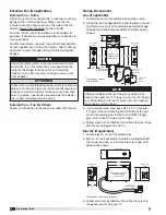
Page 12: ...Strobe if applicable If the facility does not have a fire alarm panel the horn strobe can provide visual and audible notification of a fire 1 Surface mount the horn strobe near the hood cable provided is 8 feet in length 2 Follow electrical installation instructions for horn strobe on page 15 Fire Extinguisher if applicable The system may be provided with a separate K Class 6 liter wet chemical fi...

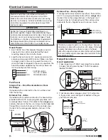
Page 13: ...nstallation should be performed by a licensed electrician Shut off power at the main breaker to prevent electrical shock when accessing electrical connections All field installation and wiring of electrical equipment must be done to meet NEC and local codes ATTENTION Confier les travaux d installation électrique à un électricien qualifié Couper l alimentation électrique au disjoncteur principal po...

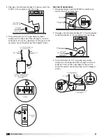
Page 14: ...NTERFACE CONTACT RATING 115 VAC 5 AMP TOP VIEW GAS SHUT OFF ASSEMBLY BOX MOUNTED BEHIND RANGE FRONT VIEW GAS FLOW VALVE RESET POWER RESET FUEL ACTIVATION CONTACT RATING 12 VAC 5 AMP AUXILIARY INTERFACE CONTACT RATING 115 VAC 5 AMP RIGHT SIDE VIEW TOP VIEW GAS SHUT OFF ASSEMBLY BOX MOUNTED BEHIND RANGE FRONT VIEW GAS ELEC DISC CABLE 6 FT CABLES FROM HOOD ATTACHED TO HOOD 9 PIN PLUG AND PLAY CABLE 4...

Page 15: ...vices Supply Fan Interlock Contacts 1 R and G terminal 2 Dry normally open contact closes when supply fan should run can be used to drive a device that controls a supply fan if MUA is necessary 3 Contacts rated to 5A and 250VAC Fire Fault Contacts 1 C6 and NO6 terminal blocks Dry normally open N O contact closes on fire fault 2 C6 and NC6 Dry normally closed N C contact that opens on fire fault 3 ...

Page 16: ... hood performance it is important for the hood to be balanced for the designed CFM For NFPA 101 compliant models 500 designed CFM is required Hood Length in NFPA 101 Compliance Ventilation External Fan Type Plenum Pressure Reading for Designed CFM High CFM High Percent of Max CFM Low Percent of Max CFM Approximate Low CFM 30 No Integral Fan Front Recirculating Not applicable 21 250 70 60 Default 2...

Page 17: ...ly locked again after a time limit default 2 hours if the hood system was configured for NFPA 101 compliance To comply with NFPA 101 this time limit cannot exceed 2 hours If the temperature reaches the cooking detection temperature setpoint default 115 F the hood turns the fan on if not already on and the fan speed control buttons are disabled The speed of the fan is no longer controlled via the u...

Page 18: ... GAUGE TANK PRESSURE VALVE TANK SOLENOID REMOTE PULL RF BLDG ALARM SHUT OFF BATTERY TEST TEST BUTTON FIRE SUPPRESSION CONTROL BOARD FIRE SUPPRESSION CONTROL BOARD ENCLOSURE INSIDE HOOD PULL PIN CURRENTLY INSTALLED IN AGENT TANK 4 The test should fail and issue six chirps indicating that the pull pin has not been removed from the tank If the result is a lesser number of chirps followed by the serie...

Page 19: ...gent dump If the stove does not shut off burner shuts off and begins to cool down additional troubleshooting is required 11 Reset the CPU board by pressing the RESET button and confirm the green indicator momentarily lights up 12 Make sure all burners are off then unlock the range via the user interface CAUTION Carefully remove the pull pin from the tank holding the release latch in place as to no...

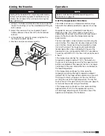
Page 20: ... and once timer reaches 0 the range will automatically lock To meet NFPA 101 life safety code compliance PW Auto Range Deactivate should be set to Enabled NOTE If the hood temperature climbs above the high temperature alarm setpoint default 180 F the range will be automatically locked This is represented by the range and lock button turning red Only upon temperatures decreasing below the high temp...

Page 21: ...rouble Detected Fire system trouble contact has been engaged Either a fire detection sensor is at fault battery voltage is low tank solenoid is not connected tank pressure is low or pull pin is not inserted properly See Fire System Diagnostics on page 25 for details Kitchen Fire Detected Fire suppression temperature sensor has detected a fire or manual pull station has been pulled Gas Reset Fault ...

Page 22: ...ching this setpoint the range will automatically be locked Default 180 F Current Hood Temperature Displays current temperature of hood System Settings Setpoints Min Fan Speed of Max 60 Max Fan Speed 70 Auto On Temp Setpoint 115 0 F Auto Fan Off Enabled High Temp Alarm Setpoint 180 0 F Current Hood Temperature 75 0 F Balance Exhaust Fan B System Settings i Configuration System Settings Configuratio...

Page 23: ...e System Discharge Only Software Version This indicates the software version running on the system controller The fault log records and stores previous faults on the system Press the blue arrow to navigate back to the Service Settings menu Balance Exhaust Fan within Systems Settings Setpoints Upon entering this menu the exhaust fan will turn on and ramp to the max speed percentage shown Connect ma...

Page 24: ...ty bolt lever simply by pulling the black handle down Keep upward pressure on the bottom of the front part of the hood while doing this After releasing the safety bolt the hood front will want to drop Slowly lower the front of the hood until the safety cable is tight Safety Bolt Lever Safety Cable 2 Behind the mesh filter in the left and right corner of the plenum are two clamps holding the hood u...

Page 25: ...every minute After 4 5 hours of a low battery indication the unit will enter the shut off sequence During fire detect mode the main unit monitors two sensors to detect high temperature indicating a fire If a fire is indicated the fire system control board will issue a fire alarm sequence see page 26 Fire Alarm Sequence NOTE Powering the fire suppression control board by inserting the battery OR pr...

Page 26: ...ible alarm place the hood into service position and press RESET button on fire suppression control board NOTE A complete system inspection and servicing must be done immediately following a kitchen range top fire Consult an authorized fire equipment company for service or proper procedure NOTE All service on the fire suppression system after actuation should be performed by authorized equipment di...

Page 27: ...To clean hood wipe grease from exposed metal surfaces on the hood interior using a clean dry cloth Stainless steel hood exterior surfaces should be cleaned with a mild detergent then polished with a high grade stainless steel polish to preserve the original luster Routinely remove metal mesh grease filter from the hood and clean using hot water and mild detergent NOTE Never use abrasive cleaners o...

Page 28: ...g high temperature setpoint Decrease cooking shut off range to allow heat to subside in hood capture tank Fire suppression control board fault Correct control board fault and reset board see Fire System Diagnostics page 25 Electric gas disconnect assembly box not wired Confirm both 10 ft plug and play control cables are connected between hood and disconnect assembly box No gas flowing to gas range...

Page 29: ...83748 Alarm Interface Assembly 483749 Manual Pull Station with 30 ft Plug and Play Cable 483750 Horn Strobe with 8 ft Plug and Play Cable 1021454 Electric Shut Off Assembly 1021455 Gas Shut Off Assembly Disconnect Box and 24VAC Valve 483752 24VAC Gas Valve ONLY 483309 Metal Mesh 18x6 inch Grease Filter 483308 Charcoal Carbon 12 75 x 4 5 inch Filter for Front Recirculating Hoods 386391 LED Light Bu...

Page 30: ...eserves the right to change specifications without notice Product warranties can be found online at accurex com either on the specific product page or in the Warranty section of the website at Accurex com Resources Warranty Our Commitment P O Box 410 Schofield WI 54476 Phone 800 333 1400 Fax 715 241 6191 Parts 800 355 5354 accurex com ...

Reviews: