background image

21

Fire Ready Hood

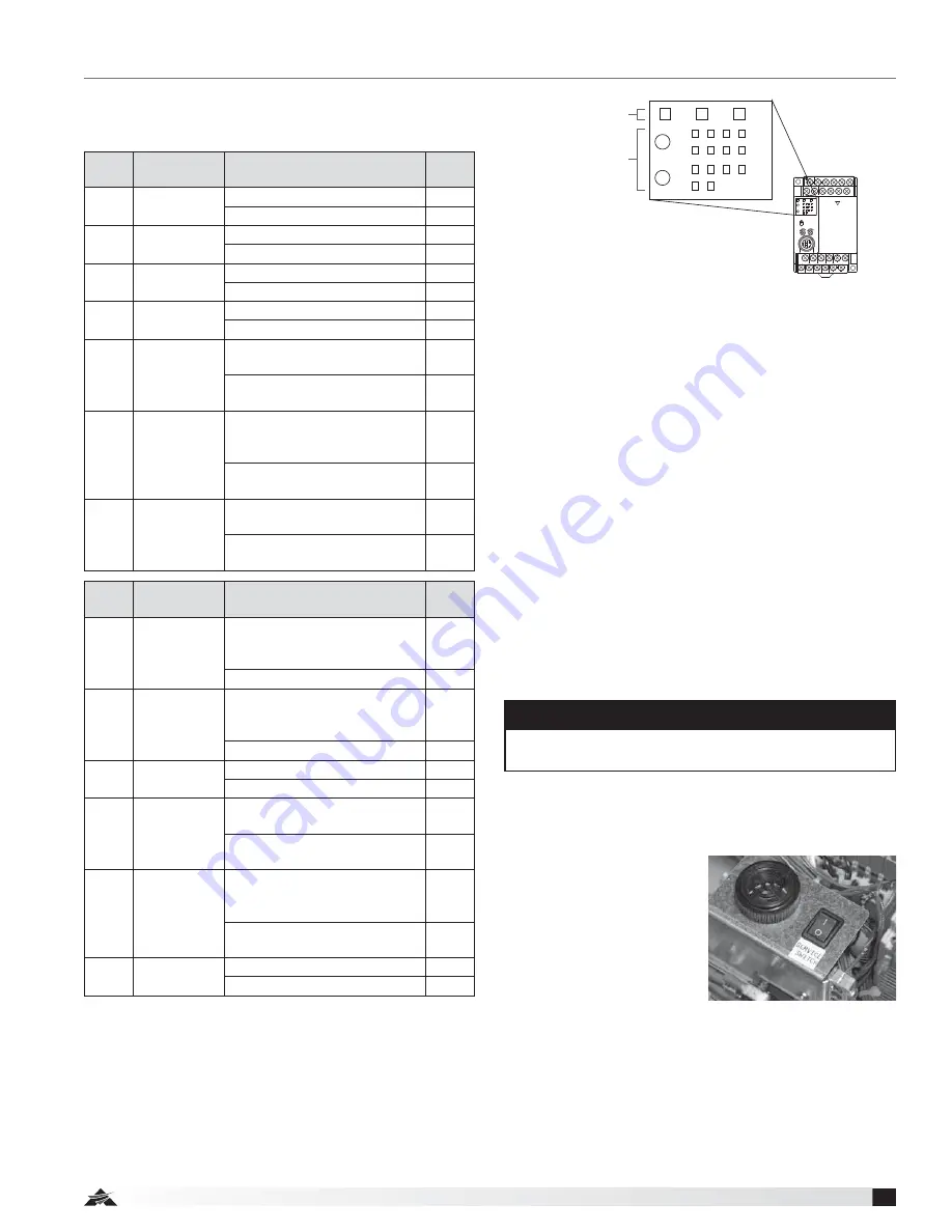
Controller Schematic

Panasonic

max.

min.

RUN

PROG. ERR.

FP-X C14

7

4

0

0

3

4

Y

X

3

V1

RUN

PROG.

V0

5

L

N

X1

X0

X2

X4

X6

COM

X3

X5

X7

Y1

Y0

0V

24V

Y5

C0

C1

C2

C3

Y4

Y3

Y2

Status display

Input/output

display

PROG.

RUN

ERR.

7

4

0

0

3

4

Y

X

3

5

The controller’s operating system is designed to 
enhance the functionality of the unit and the safety of 
the cooking environment.

On the controller, there are two rows of LED indicators 
next to the X (inputs) and two rows of LED’s on the Y 
area (outputs).

Alarm Connections

Alarm Outputs:

  The other function of the controller 

is to report alarms from the system either for a system 
fault or as a result of a system discharge. Refer to 
Fire Alarm System Connections on page 14 in this 
installation manual for information on how to connect 
the alarm outputs.

Output Y1 and common C1 are configured to close with 
the discharge of the extinguisher tank. This condition is 
determined by the controller with the low pressure input 
from the switch and a high temperature condition from 
the 190°F rated thermostat. Both conditions must be 
present in order for this output to trigger.

Note that the microswitch outputs are dry contact type, 
rated for low voltage, and can be normally open (NO) or 
normally closed (NC), with a common. Therefore do not 
produce any current or voltage output.

Service Switch:

  The black switch next to the controller 

and internal audible alarm is the service switch. It can 
be switched on or off. When it is switched to on, the 
remote alarm and local 
alarm are deactivated. Its 
purpose is to allow service 
to be conducted and 
components tested without 
setting off the alarm. Once 
testing or service is done, 
turn the service switch to 
off for normal operation. 
NOTE: LED will flash orange 
and green.

Service Switch  

in the OFF position

LED 

Label

Input 

Function

Scenario

LED 

State

X0

Hose 

Switch

Hose in place

On

Hose disconnected

Off

X1

Reset 

Switch

When switch is depressed

On

Switch not pressed

Off

X2

Pressure 

Switch

Pressure okay

On

Pressure failure

Off

X3

Service 

Switch

Servicing unit

On

Normal operation

Off

X4

Low 

Temperature 

Switch

Both low temp thermostats 
below 150°F

On

Either thermostat at or above 
150°F

Off

X5

Remote  

and  

Local Alarms

Alarms are configured for 
normally closed (jumper 
installed)

On

Alarms are configured for 
normally open (no jumper)

Off

X6

High 

Temperature 

Switch

High temperature thermostat 
below 190°F

On

High temperature thermostat 
at or above 190°F

Off

LED 

Label

Output 

Function

Scenario

LED 

State

Y0

Output for 

Local Alarm

Low gas switch activates OR 
hose switch activates OR high 
temperature switch activates

On*

Normal operation

Off*

Y1

Output for 

Remote 

Alarm

Loss of pressure AND high 
temperature (fire suppression 
discharge)

On*

Normal Operation

Off*

Y2

Normal 

Condition

Alarm condition

On

Normal condition

Off

Y3

Fan

When controller turns the fan 
on

On

When controller is not running 
the fan

Off

Y4

Power 

Disconnect

When power is being set 
to gas/electric disconnect 
(normal operation)

On

When power is lost to gas/
electric disconnect

Off

Y5

Horn

Horn is on

On

Horn is off

Off

NOTE

Pressing the reset button will not turn off alarm. Unit 
needs to be recharged to reset alarm.

* The LED’s state depends on whether the alarm contacts are 

set up for normally open or normally closed. These contacts 
are set up for normally open from the factory (LED’s illuminate 
during alarm). To configure the fire contacts for normally 
closed state (LED’s illuminate on no alarm), a jumper must 
be placed between two terminals. Please see page 14 for 
additional information.

Summary of Contents for XRRS

Page 1: ...the American Society of Heating Refrigeration and Air Conditioning Engineers ASHRAE and the local code authorities When cutting or drilling into wall or ceiling do not damage electrical wiring and other hidden utilities To reduce the risk of fire or electric shock do not use this range hood with an additional speed control device Ducted fans must always be vented to the outdoors To reduce the risk ...

Page 2: ...referencing the delivery receipt or packing list Inspect each crate or carton for shipping damage before accepting delivery Alert the carrier of any damage detected The customer will make notation of damage or shortage of items on the delivery receipt and all copies of the bill of lading which is countersigned by the delivering carrier If damaged immediately contact your Accurex Representative Any...

Page 3: ...ft shielded control wire for plug and play connection Electrical disconnect box optional 6 ft shielded control wire for plug and play connection 8 ft of metal clad wire for gas disconnect electrical disconnect connection marked with black tape Remote switches ADA optional Manual Pull Kit optional consisting of the following Pull Box 1 Pull Face 1 Elbow Pulley 3 25 ft Cable and Pin The ClockBox opt...

Page 4: ...e to Fan provided Power Disconnect Cable provided 110 VAC Supply Cable provided Wall Mount Fan Box with Access Cover for Service and Mounting provided Wall Mount Fan Box with Access Cover for Service and Mounting provided Cabinet Wall Cap by others Range Hood provided Airflow 3 x 12 in Ductwork Soffit Power Disconnect Cable provided 110 VAC Supply Cable provided Cabinet Range Hood provided Airflow So...

Page 5: ... Yes Exterior Wall Fan Vertical Duct 550 20 feet Maximum duct length equals horizontal and vertical duct runs plus duct components such as fittings elbows and transitions For installations requiring vertical duct venting to an inline fan and NFPA 101 compliance the hood should be adapted from a 7 inch round duct access hole to a minimum 12 inch duct For installations requiring vertical duct venting...

Page 6: ...h the fan box Accessories Location restrictions will apply if the hood system supplied is provided with any of the optional accessories ClockBox Remote ADA Switches Manual Pull Station 2 Attach square duct collar to the bottom of the fan box with included hardware 3 Attach the fan box to the mounting bracket with included 8 32 nuts then complete the installation on the manual pull kit conduit and ...

Page 7: ...ting points must be secured to studs or drywall hangers C Rear access to junction box connection D Primary access point for connections to junction box E Secondary access point for connections to hood options accessories F Additional mounting points Secure minimum of three 3 screws per row Cabinet Front Cabinet Front Cabinet Bottom Electrical Access Hole 7 inch Round Duct Access Hole C L 5 15 16 i...

Page 8: ...ove the safety key from the actuator arm by rotating and lifting straight upwards The system will not actuate without completing steps 4 and 5 6 Rotate hood to wall and thread the three thumb nuts to the bolts in the mounting plate Check page 18 for location of thumb nuts Installing Hood onto Mounting Bracket 4 Remove the safety pin identified with the yellow CAUTION flag from the trigger on top of ...

Page 9: ...inlet and outlet flanges Wall Mounted Fan Fasten the fan box to an external wall via the four 0 27 inch mounting holes Run electrical through the 0 81 inch hole towards the top right corner of the box Attach ductwork using duct sealant caulk or tape to all seams to prevent air leakage and maximize air performance For best results use as few elbows or transitions as possible If necessary long radius...

Page 10: ...e of the face plate Given this the hole should be about 6 3 8 by 8 3 4 inch The relay box has been designed to fit in a standard 2x4 studded wall 2 If you haven t already done so run wiring from the junction box location on the unit mounting plate to the power disconnect box location and string through one of the knockouts in the box 3 Make all wiring connections and secure face plate to box in wal...

Page 11: ... the actuator arm Step 3 Install Cable and Pin to hood Thread the cable through the conduit with the pin reaching the unit Remove the grease filter In the upper right corner find the two pulleys as illustrated Hold the rear most pulley in place From the top of the unit replace its pin with the one on the cable Push the pin through the pulley until you hear it click in place Go back to the actuator a...

Page 12: ... applicable codes and regulations Shut off power at the main breaker to prevent electrical shock when accessing electrical connections All field installation and wiring of electrical equipment must be done to meet NEC and local codes Electrical Installation Range Supply Line 208 220 VAC 50A max supplied by others Hood Supply 110 120 VAC 15A Metal clad wire from 110 120 VAC supply line 12 2 8 ft le...

Page 13: ...0 VAC Supply Line Red Tape Green Ground Wire nut inside power disconnect box Green Ground Black Hot 110 120 VAC 14 2 Hood White Neutral Black Hot 110 120 VAC Junction Box White Neutral Contactor 50A Supplied Power Disconnect Box 8 x 6 x 4 Back Support Mounting Bracket GND NEUT HOT GND NEUT HOT H N H H H Metal Clad Wire from 110 120 VAC Supply Line Red Tape 6 Position Orange Connector 6 Position Gr...

Page 14: ...has discharged You may use either one connection or both depending on your situation When there is a fault a buzzer in the unit will sound and the power disconnect will turn off Local Alarm Connection Connect to output Y0 and common C0 Remote Alarm Connection Connect to output Y1 and common C1 To connect to the alarms it is preferred that you use a spade terminal connector supplied but a stripped ...

Page 15: ...ow MP1 Main Power Connector FP2 Fan Connector SW1 Main Power Switch SW2 Light Switch SW3 Service Switch SW4 Reset Switch SW5 Optional ADA Light SW6 Optional ADA Fan HSW1 Hose Switch HITH1 High Temp Thermostat 190 F LOTH1 2 Low Temp Thermostat 150 F FSP1 Fan Speed Controller 4 0 FLA FAN Inline or Recirc Fan CAP1 Capacitor for Recirc Fan 10 UF M1 Stove Disconnect 40 FLA 50 A RES LIGHT Hood Light 60 ...

Page 16: ... will be maintained for as long as there is time left at the ClockBox it will open the contact in the timer stopping the supply line to the Power Disconnect which in turn will shut off the stove NOTE Some electric stoves ranges have a warning light to alert the user that the burners coils are hot These warning lights will be off since the supply line powering the stove range is not present 120VAC ...

Page 17: ...l system is not enabled and this reset button needs to be pressed In doing so the Status LED below the reset switch will turn from red to green Environmental Monitoring Pre Suppression Functions The controller operating system is designed to enhance the functionality of the unit and the safety of the cooking environment The system relies on input from a set of thermostats to control the fan and sh...

Page 18: ...ent On ducted installations remove the two thumb nuts located at the top inside near the fan intake Slowly lower the unit 4 The unit will now freely pivot downward to a stop position A safety cable is provided to prevent the unit from falling or lowering too far 5 Place safety pin in the tank valve to avoid accidental discharge With the unit in this position basic servicing and cleaning may be per...

Page 19: ...ure 3 NOTE Main Screen will always show available time System is pre set to countdown remaining time FIGURE 2 1 Factory preset master password 06412 2 Enter password 06412 and then press the enter symbol FIGURE 3 1 Press Timer Mgmt to modify the timer value See Figure 4 for timer management screen 2 Press Password Mgmt to add modify delete passwords See Figure 5 for password management screen FIGU...

Page 20: ...talled Remove the plastic break rod from the pull face with an allen wrench refer to manual pull station appendix for more detailed information on this Pull the handle to actuate the unit Refer to the Manual Pull Kit section on the method to return the pull station to an operational state 2 The unit can be actuated one of two ways A Cut Test Links Replace the actuator arm s safety key Loosen the t...

Page 21: ...rn the service switch to off for normal operation NOTE LED will flash orange and green Service Switch in the OFF position LED Label Input Function Scenario LED State X0 Hose Switch Hose in place On Hose disconnected Off X1 Reset Switch When switch is depressed On Switch not pressed Off X2 Pressure Switch Pressure okay On Pressure failure Off X3 Service Switch Servicing unit On Normal operation Off ...

Page 22: ...ns on for 3 minutes after you lower temperature or put red wire back on h Hood remains powered Self Monitoring System These functions are to be checked at start up Low Temperature Switches HOW TO TEST FUNCTION a Use heat gun on either left or right low temp switch b Fan turns on c Fan remains on for three minutes after temperature falls below 150ºF High Temperature and Low Pressure Switches HOW TO...

Page 23: ...ing before attempting any cleaning Using water to clean any appliance that contains hot grease or cooking oils may result in violent steaming or splattering How to Reset the Suppression System Resetting and testing release mechanisms remote pull and fusible links Reset detection system by completing the following steps 1 Remove extinguisher tank 2 Make sure tension arm cable is in the released sla...

Page 24: ... will energize into its normal operating open position 2 Examine burners for gaseous odor If gas odor exists turn off power switch which will cause the gas valve to close and shut off gas supply Clear gas fumes by opening windows and doors and then correct gas leak before proceeding 3 Reset gas valve again and if there is no gaseous odor pilot lights may be ignited at this time Gas stoves with a p...

Page 25: ... or after 12 months of use Inspection Procedures Maintaining the System WARNING The protective caps stay on the nozzles at all times In the event of a discharge the caps will blow off WARNING If grease build up on the cable system is not kept to a minimum the cable could become stiff and will not discharge the suppressant in the event of a fire 10 Year Maintenance Hydrostatic testing and new liqui...

Page 26: ...C as replacement 479690 Fire Ready 60W Shatterproof Bulb pack of 2 479691 Fire Ready Fusible Links 212 F 3 links 479692 Fire Ready Fusible Links 280 F 3 links 479693 Fire Ready Nozzle Caps set of 10 479694 Fire Ready Wire Rope Assembly Set Hood Width of 30 inches 479695 Fire Ready Wire Rope Assembly Set Hood Width of 36 inches 479696 Fire Ready Replacement Charcoal Filters F Calibrations pack of 1...

Page 27: ...__________________ _________________________________________________ _________________________________________________ Date ___________________Time _____________ AM PM Notes ___________________________________________ _________________________________________________ _________________________________________________ _________________________________________________ ________________________________...

Page 28: ...curex reserves the right to change specifications without notice Specific Accurex product warranties are located on accurex systems com within the product area tabs and in the Library under Warranties Our Commitment P O Box 410 Schofield WI 54476 Phone 800 333 1400 Fax 715 241 6191 Parts 800 355 5354 www accurex com ...

Reviews: