background image

Upblast Centrifugal Roof Exhaust

4

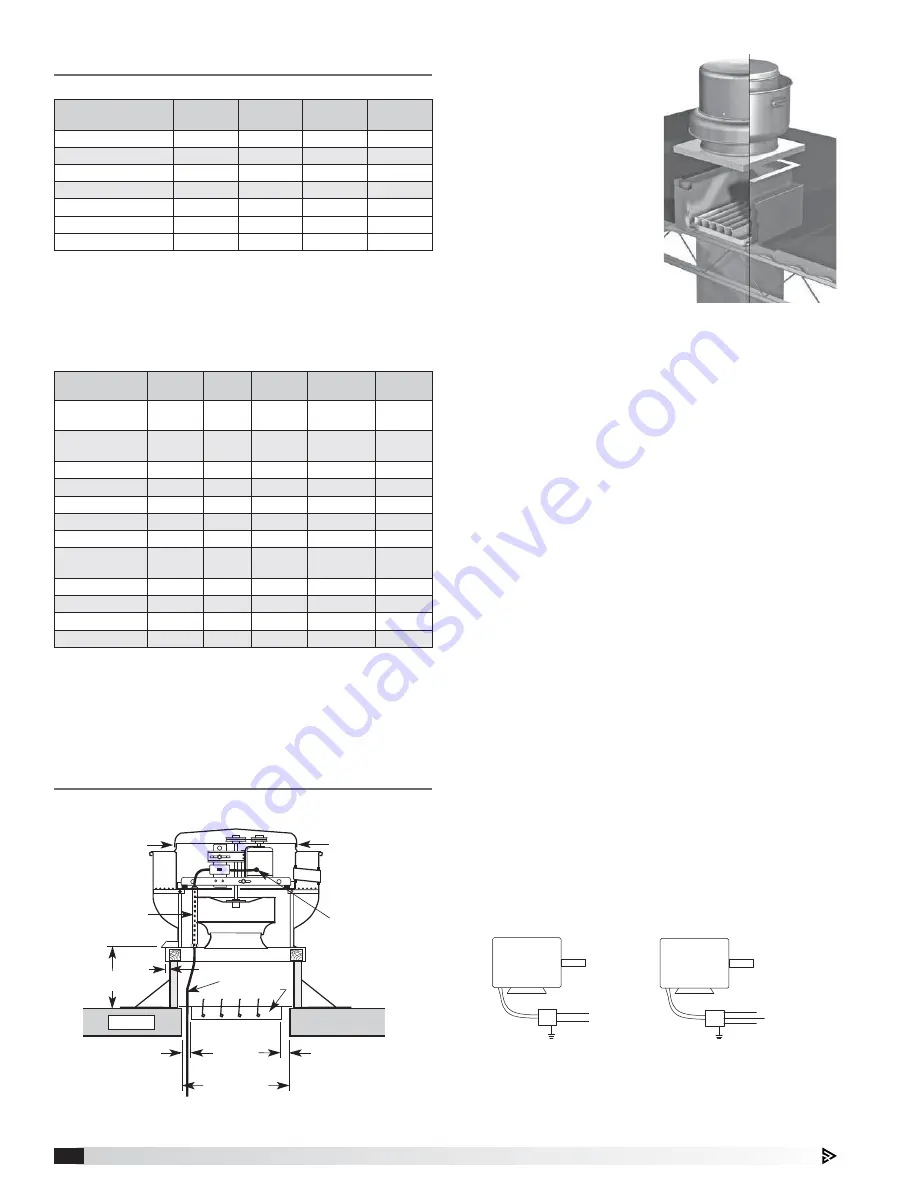
Figure 4 - Typical Roof Mounting Installation

Installation

General Ventilation Installation

8 or 12 in. min.

(203 or 305 mm)

Recommended

Roof Opening

Recommended

Duct and

Damper Size

Wiring by

Others

Factory Wired
Motor to
Disconnect

Roof Deck

Damper

Screw

Screw

Conduit

Chase

3/4 in.

(19 mm)

1¼ in.

(32 mm)

1¼ in.

(32 mm)

Direct Drive

Model Size

Curb Cap

Damper

Roof 

Opening

*Approx. 

Weight

060, 070

17 

(432)

(203)

10

1

2


(267)

29 

(13)

080, 090, 095

19 

(483)

10 

(254)

12

1

2


(318)

40 

(18)

099, 101, 121, 131

19 

(483)

12 

(305)

14

1

2


(368)

67 

(30)

141, 161

22 

(559)

16 

(406)

18

1

2


(470)

90 

(41)

180, 200, 200HP

30 

(762)

18 

(457)

20

1

2


(521)

142 

(64)

240, 240HP

34 

(864)

24 

(610)

26

1

2


(673)

175 

(79)

300, 300HP

40 

(1016)

30 

(762)

32

1

2


(826)

313 

(142)

•  All dimensions are in inches 

(millimeters)

. *Approximate weight shown in  

lbs. 

(kg.)

 is the largest cataloged open drip proof motor. 

•  “Curb Cap” is the inside dimension of the curb cap

•  The roof curb should be 1½ in. 

(38 mm)

 less than the curb cap to allow for 

roofing and flashing.

•  Roof opening is a square dimension.

1.  On the roof surface, 

cut an appropriate 
sized hole and follow 
manufacturer’s 
instructions on curb 
installation. Caulk and 
flash the curb to ensure 
a water tight seal.

2.  If unit is equipped with 

a backdraft damper, it 
should be installed now.

3.  Remove motor cover. 

Access to the motor 
compartment is 
accomplished by 
removing the screws as shown in Figure 3

page 2.

4a. On 

belt drive

 fans, use the lifting lugs on the drive 

frame or bearing plate to lift and place the unit on 
top of roof curb. Refer to Figure 2, page 2. 

4b. On 

direct drive

 fans, lift and place the unit on 

top of roof curb using hooks under the horizontal 
supports. Refer to Figure 1, page 2.

5.  Secure fan to curb using a minimum of eight lag 

screws, metal screws or other suitable fasteners. 
Shims may be required depending upon curb 
installation and roofing material.

6.  Verify power line wiring is de-energized before 

connecting fan motor to power source.

7.  For commercial kitchen and UL Listed emergency 

smoke control applications, the electrical supply 
must enter the motor compartment through 
the breather tube. For other non-flammable 
applications, the electrical supply can be routed 
through the conduit chase between the curb cap 
and the bottom of the motor compartment.

8.  Connect power supply wiring to the motor as 

indicated on the motor nameplate or terminal box 
cover. Check the power source for compatibility 
with the requirements of your equipment.

9.  Check fan wheel for free rotation, recenter if 

necessary. Check setscrew(s) for tightness.

10.  Check all fasteners for tightness.

11.  Mount and wire safety disconnect switch under 

motor cover. Wire control switches at ground level, 
refer to Figure 6.

12.  Replace motor cover.

Figure 5 - Roof Curb Installation

Dimensional Data

Figure 6 - Typical Wiring Diagram

MOTOR 

L1 

115/208-230/60/1 

208-230/460/60/3

MOTOR

J-BOX

J-BOX 

SUPPLY VOLTAGE 

SUPPLY VOLTAGE

L2 

L1

L2

L3

Belt Drive

Model Size

Curb Cap

Shaft 

Bearings

Damper

Roof

Opening

*Approx. 

Weight

099, 101, 101HP, 
121, 131

19 

(483)

3

4


(19)

12 

(305)

14

1

2


(368)

66 

(30)

141, 141HP, 161, 
161HP

22 

(559)

3

4


(19)

16 

(406)

18

1

2


(470)

87 

(39)

161XP

22 

(559)

(25)

16 

(406)

18

1

2


(470)

87 

(39)

180

30 

(762)

3

4


(19)

18 

(457)

20

1

2


(521)

126 

(57)

180HP

30 

(762)

(25)

18 

(457)

20

1

2


(521)

126 

(57)

200

30 

(762)

3

4


(19)

18 

(457)

20

1

2


(521)

142 

(64)

200HP

30 

(762)

(25)

18 

(457)

20

1

2


(521)

142 

(64)

220, 220HP, 240, 
240HP, 240 XP

34 

(864)

(25)

24 

(610)

26

1

2


(673)

175 

(79)

300, 300HP, 300XP

40 

(1016)

(25)

30 

(762)

32½ 

(826)

313 

(142)

360, 360HP, 360XP

46 

(1168)

1

1

(32)

36 

(914)

38

1

2


(978)

440 

(200)

420

52 

(1321)

1

1

4


(32)

42 

(1067)

44

1

(1130)

578 

(262)

480

58 

(1473)

1

1

(38)

48 

(1219)

50

1

(1283)

675 

(306)

•  All dimensions are in inches 

(millimeters)

. *Approximate weight shown in  

lbs. 

(kg.)

 is the largest cataloged open drip proof motor. 

•  “Curb Cap” is the inside dimension of the curb cap

•  The roof curb should be 1½ in. 

(38 mm)

 less than the curb cap to allow for 

roofing and flashing.

•  Roof opening is a square dimension.

Summary of Contents for XRUB Belt Drive

Page 1: ...icals Replace cord immediately if damaged 6 Verify that the power source is compatible with the equipment Direct Drive Upblast Centrifugal Exhaust Fan These fans are specifically designed for roof and wall mounted applications The maximum continuous operating temperature for fan sizes 099 300 is 400 F 204 C and for fan sizes 060 095 is 130 F 54 C Direct drive fans are available with nominal wheel d...

Page 2: ...oid lifting fans in a way that will bend or distort fan parts Never pass slings or timbers through the venturi of fan Fans with special coatings or paints must be protected in handling to prevent damage 4 Drive Frame Lifting Points 2 Bearing Plate Lifting Points Hook With Safety Latch Supplied by others Figure 2 Screw Screw Figure 3 Figure 1 Handling Direct and Belt Drive Units Lift Direct Drive u...

Page 3: ...isture proof paper or polyethylene sheathing Aisles between parts and along all walls should be provided to permit air circulation and space for inspection IMPORTANT Installation troubleshooting and parts replacement are to be performed only by qualified personnel Consult and follow all applicable national state and local codes They will supercede this document Outdoor Fans designed for outdoor ap...

Page 4: ...terial 6 Verify power line wiring is de energized before connecting fan motor to power source 7 For commercial kitchen and UL Listed emergency smoke control applications the electrical supply must enter the motor compartment through the breather tube For other non flammable applications the electrical supply can be routed through the conduit chase between the curb cap and the bottom of the motor co...

Page 5: ...er DO NOT install it Perform steps 3 12 of General Ventilation Installation IMPORTANT The size of the duct must be equal to or larger than the inlet opening of the fan To comply with NFPA 96 the fan discharge must be a minimum of 40 in 1016 mm above the roof surface and a minimum of 10 ft 3048 mm from any building air intake Per NFPA 96 ductwork to an upblast discharge exhaust fan must be construc...

Page 6: ... Hinge Kit Fan to Curb Mounting 5 16 inch 7 9 mm self drilling fasteners are to be installed on each side of fan with one fastener 4 inches 102 mm from each edge and one fastener in the center Figure 9 Fasteners are to be equally spaced Mounting for Severe Duty Installation Optional Hinged Base Mounting For installations that include the optional hinged base accessory the fan must be secured to th...

Page 7: ...NT La turbine doit impérativement tourner dans le bon sens Une rotation en sens inverse entraînerait de mauvaises performances de soufflage une surcharge du moteur voire un grillage du moteur CORRECT WRONG WRONG WRONG Figure 15 Belt Drive Pre Starting Belt Tension Checks 4 Always loosen tension enough to install belts without stretching Do not force belt s see Figure 14 Forcing belts will break th...

Page 8: ... system in full operation and all ductwork attached measure current input to the motor and compare with the nameplate rating to determine if the motor is operating under safe load conditions 6 Keep inlets and approaches to fan clean and free from obstruction IMPORTANT Adjust tighten belt tension after the first 24 48 hours of operation 9 The adjustable motor pulley is factory set for the RPM speci...

Page 9: ...gn the unthreaded holes of the hub with the threaded holes of the tapered bushing Reverse Mounting Slide the wheel and hub assembly onto the fan shaft followed by the bushing and shaft key If present use the keyway setscrew to hold the shaft key and bushing in place but DO NOT overtighten as this can damage the bushing Align the unthreaded holes of the tapered bushing with the threaded holes of th...

Page 10: ...can be classified in two groups relubricating and non relubricating All non relubricating bearings on belt drive fans are factory lubricated and require no further lubrication under normal use between 20º to 180ºF 29º to 82ºC in a relatively clean environment 8 On belt drive fans the standard cast pillow block bearings are factory lubricated and are provided with external grease fittings Annual lubr...

Page 11: ...ey Drive Frame Assembly Vibration Isolators Vertical Support Windband Wheel Breather Tube Birdguard in tube Hoodband Disconnect Switch Hoodband Bracket Horizontal Support Belt Drive Direct Drive Curb Cap Venturi Wheel Vibration Isolators Motor Hoodband Conduit Chase Horizontal Support Vertical Support Hood Clip Motor Cover Birdguard Breather Tube Motor Support Pan Disconnect Drain Trough Windband ...

Page 12: ...e ductwork Check proper operation of face and bypass dampers Check filters and access doors Fan does not operate Electrical supply Check fuses circuit breakers Check for switches off Check for correct supply voltage Drive Check for broken belts Tighten loose pulleys or belts Motor Ensure motor is correct horsepower and not tripping overload protector Motor overloads or overheats Lubrication Check ...

Reviews: