background image

Steel Grease Fan

4

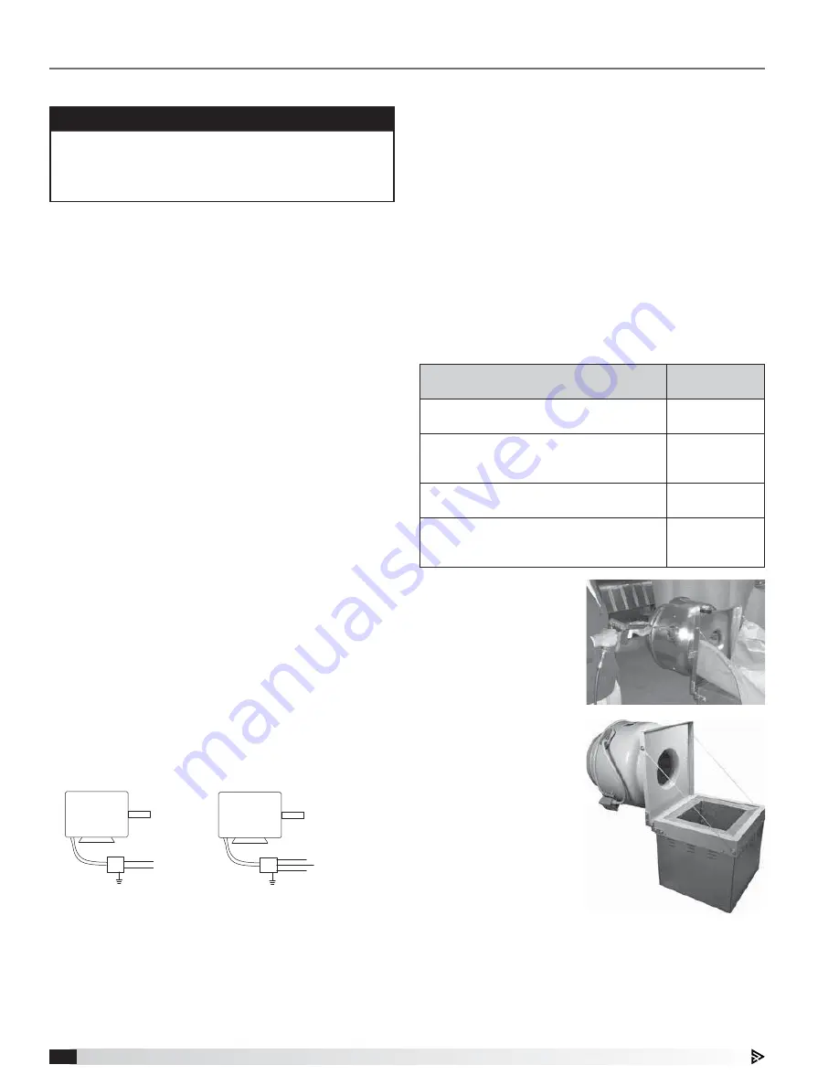
Figure 5

 15. Hinged Base: 

During installation 
of the hinged base, 
it is important not 
to allow the fan to 
go beyond 90º, see 
Figure 5.

Table 1: Exhaust System Inspection Schedule

Type or Volume of Cooking

Frequency 

Check

Systems serving solid fuel cooking 
operations

Monthly

Systems serving high-volume cooking 
operations, such as 24 hour cooking,  
char broiling, or wok cooking

Quarterly

Systems serving moderate-volume 
cooking operations

Semiannually

Systems serving low-volume cooking 
operations, such as churches, day camps, 
seasonal business, or senior centers

Annually

Figure 4

 14. Clean-Out Port: 

Position the 
clean-out port so 
it is on the side of 
unit when hinged 
open, see Figure 4.

Installation

Typical Roof Mounting Installation

  1.  On the roof surface, cut an appropriate sized hole 

and follow manufacturer’s instructions on curb 
installation. Caulk and flash the curb to ensure a 
water tight seal.

  2.  Remove motor cover. Access to the motor 

compartment is accomplished by removing the 
screws as shown on page 2, Figure 2. 

  3.  Use the lifting lugs on the drive frame to lift and 

place the unit on top of roof curb. Refer to page 2, 
Figure 1.

  4.  Secure fan to curb using a minimum of suitable 

fasteners. Shims may be required depending upon 
curb installation and roofing material.

  5.  Verify power line wiring is de-energized before 

connecting fan motor to power source.

  6.  For commercial kitchen applications, the electrical 

supply must enter the motor compartment through 
the breather tube. For other non-flammable 
applications, the electrical supply should also be 
routed through the breather tube. 

  7.  Connect power supply wiring to the motor as 

indicated on the motor nameplate or terminal box 
cover. Check the power source for compatibility 
with the requirements of your equipment.

  8.  Check fan wheel for free rotation, recenter if 

necessary. Check set screw(s) for tightness.

  9.  Check all fasteners for tightness.

 10.  Mount and wire safety disconnect switch under 

motor cover. Wire control switches at ground level, 
refer to Figure 3.

 11.  Replace motor cover.


MOTOR 

L1 

115/208-230/60/1 

208-230/460/60/3

MOTOR

J-BOX

J-BOX 

SUPPLY VOLTAGE 

SUPPLY VOLTAGE

L2 

L1

L2

L3

Figure 3 - Typical Wiring Diagram

IMPORTANT

Installation, troubleshooting and parts replacement 
are to be performed only by qualified personnel. 
Consult and follow all applicable national, state and 
local codes as they will supercede this document.

 12.  A drain trough is provided on all fans for single-

point drainage of water and residue. Some means 
for collection of this residue must be provided, 
either a container directly under the trough or use 
of an adapter and pipe to carry the residue to a 
remote collection point. An optional grease trap 
with water separator baffle is available from your 
representative.

 13.  A clean-out port and hinged base are also provided 

on all units. They aid the cleaning process through 
additional access to the wheel. The fan is designed 
for the worst cooking conditions, such as char 
broilers, solid fuel cooking or oriental cooking.


  Table 1 shows the suggested exhaust system 

inspection schedule published in NFPA 96.

Summary of Contents for XRUBS-140

Page 1: ...des as well as the National Electrical Code NEC and the National Fire Protection Agency NFPA where applicable Follow the Canadian Electric Code CEC in Canada 2 The rotation of the wheel is critical It must be free to rotate without striking or rubbing any stationary objects 3 Motor must be securely and adequately grounded 4 Do not spin fan wheel faster than max cataloged fan RPM Adjustments to fan...

Page 2: ...ocal code authorities for specific requirements Storage Fans are protected against damage during shipment If the unit cannot be installed and operated immediately precautions need to be taken to prevent deterioration of the unit during storage The user assumes responsibility of the fan and accessories while in storage The manufacturer will not be responsible for damage during storage These suggesti...

Page 3: ...heel by hand ten to fifteen revolutions to distribute lubricant in motor If paint deterioration begins consideration should be given to touch up or repainting Fans with special coatings may require special techniques for touch up or repair Machined parts coated with rust preventive should be restored to good condition promptly if signs of rust occur Immediately remove the original rust preventive c...

Page 4: ...motor compartment through the breather tube For other non flammable applications the electrical supply should also be routed through the breather tube 7 Connect power supply wiring to the motor as indicated on the motor nameplate or terminal box cover Check the power source for compatibility with the requirements of your equipment 8 Check fan wheel for free rotation recenter if necessary Check set ...

Page 5: ...iances label Grease Trap Installation The polypropylene grease trap is designed to collect grease residue and avoid drainage onto roof surface Follow all local codes as well as the National Fire Protection Agency NFPA where applicable NFPA 96 Upblast fans shall have a drain directed to a readily accessible and visible grease receptacle not to exceed 1 gal 3 8L Refer to Document 476370 Grease Trap ...

Page 6: ... arms and drive frame angles in the same manner Four 4 fasteners in total Identical fasteners on opposing side must also be loosened 9 If adjustments are made it is very important to check the pulleys for proper alignment Misaligned pulleys lead to excessive belt wear vibration noise and power loss See Figure 11 CORRECT WRONG WRONG WRONG Figure 11 Figure 12 11 Belt tension should be adjusted to al...

Page 7: ...nt See Figure 9 on page 6 4 When the fan is started observe the operation and check for any unusual noises 5 With the system in full operation and all ductwork attached measure current input to the motor and compare with the nameplate rating to determine if the motor is operating under safe load conditions 6 Keep inlets and approaches to fan clean and free from obstruction Inspection Inspection of...

Page 8: ...enance are to be performed only by qualified personnel who are familiar with local codes and regulations and who are experienced with this type of equipment Motor maintenance is generally limited to cleaning and lubrication where applicable Cleaning should be limited to exterior surfaces only Removing dust buildup on motor housing ensures proper motor cooling Greasing of motors is only intended whe...

Page 9: ...requent lubrication is required A good quality lithium base grease conforming to NLGI Grade 2 consistency such as those listed in Table 3 may be used Dampers must open fully Use motorized dampers in low airflow applications to reduce losses Avoid sharp turns or entrance conditions which cause uneven flow Use turning vanes in elbows to reduce adverse effects Provide uniform airflow at fan inlet to ...

Page 10: ...tage Drive Check for broken belts Tighten loose pulley or belts Motor Ensure motor is correct horsepower and not tripping overload protector Motor overloads or overheats Lubrication Check for excessive or insufficient grease in the bearing Mechanical Replace damaged bearing Relieve excessive belt tension Align bearings Check for bent shaft Belt slippage Adjust tension or replace bad belts see page ...

Page 11: ...meplate with model number and serial number embossed This information will assist the local representative and the factory in providing service and replacement parts Before taking any corrective action make certain unit is not capable of operation during repairs NOTE For replacement the windband vertical supports drain trough and curb cap with mounting holes comes as one complete assembly Vertical...

Page 12: ...eserves the right to change specifications without notice Product warranties can be found online at accurex com either on the specific product page or in the Warranty section of the website at Accurex com Resources Warranty Our Commitment P O Box 410 Schofield WI 54476 Phone 800 333 1400 Fax 715 241 6191 Parts 800 355 5354 accurex com ...

Reviews: