Slide Installation
Slide Installation
Install Cabinet Member
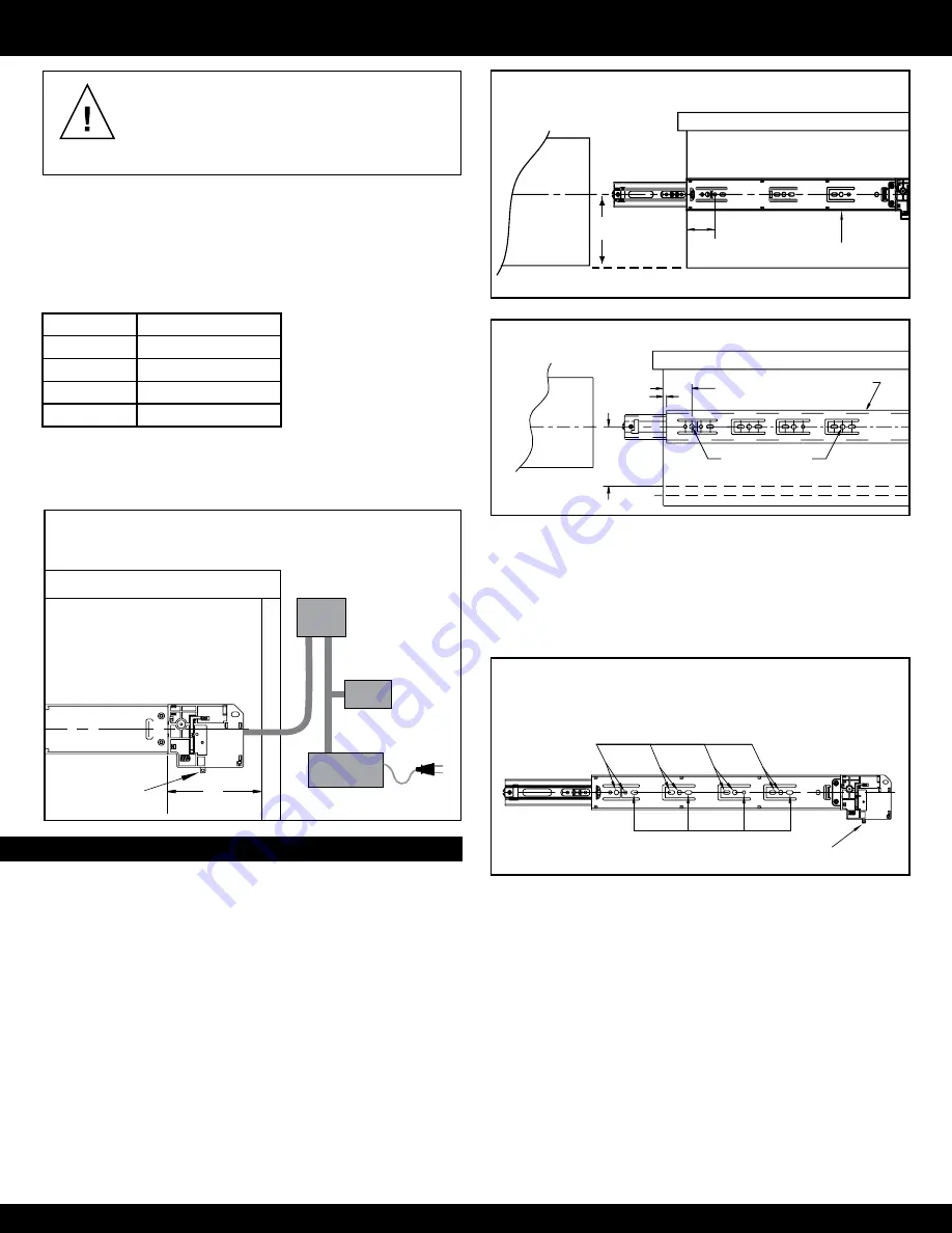
1. Separate the slide members by first actuating the manual
override located on the locking mechanism.
2. Then, lift the disconnect lever to release the inner (drawer)
member.
3. Overlay drawer front:
- Conventional mounting, see Figure 2.
- 32 mm system mounting, see Figure 3.
A38EL Components and Interior Cabinet Depth
Conventional mounting - Cabinet
System Holes
2.0 mm
38.1
mm
For overlay
drawer front
37.0 mm
Cabinet
Member
32 mm system mounting - Cabinet
Figure 3.
Activation
Device
Power Supply
The slide is connected to the activation
device. The activation device is
connected to the powersource, which
powers the activation device and
locking mechanism. The activation
device and the power supply are
included in the Proximity Kit
ACPROX-US-Kit1 (optional)
3''
minimum
HUB
Access to
manual override
Cabinet Member
1 7/8"
1 1/2"
Drawer
For overlay
drawer front
IMpORTANT:
• Be sure the interior cabinet depth allows for an additional 3"
beyond the length of the slide to provide room for the locking
mechanism and wiring (Figure 1). See the chart below for
minimum cabinet depth. For inset drawers, be sure to provide
sufficient cabinet depth to allow slide setback.
Slide Length
Min. Cabinet Depth
16"
19"
18"
21"
20"
23"
22"
25"
• Slides will not function properly if side space is less than .50"
[12.7 mm]. For optimum performance, construct drawer 1-1/16"
[27.0 mm] smaller than the opening of the cabinet.
Installation Instructions
Figure 1.
2
WARNING!
Before installing the drawer, insure
you have access to the lock’s manual override
lever or the activation device must be connected
and working properly.
Otherwise, you will not be
able to unlock the slide and open the drawer.
Figure 2.
4. Inset drawer front:
Slide setback is the thickness of the drawer front plus 1/8"
[3.2 mm].
5. Use only the 32 mm system holes or the wood screw holes
located at the tip of the breathing tabs. Do not use any other
holes on the cabinet member for mounting (Figure 4).
Install Drawer Member
1. See Figure 5 for drawer member setback.
2. Install the drawer member with a screw through the cam adjuster
and a screw through a hole or slot at the rear (see Figure 5).
Use all mounting tabs to achieve load rating.
Figure 4.
No
Yes
Manual Override
Cabinet Member Fastener Locations


