Technical Data
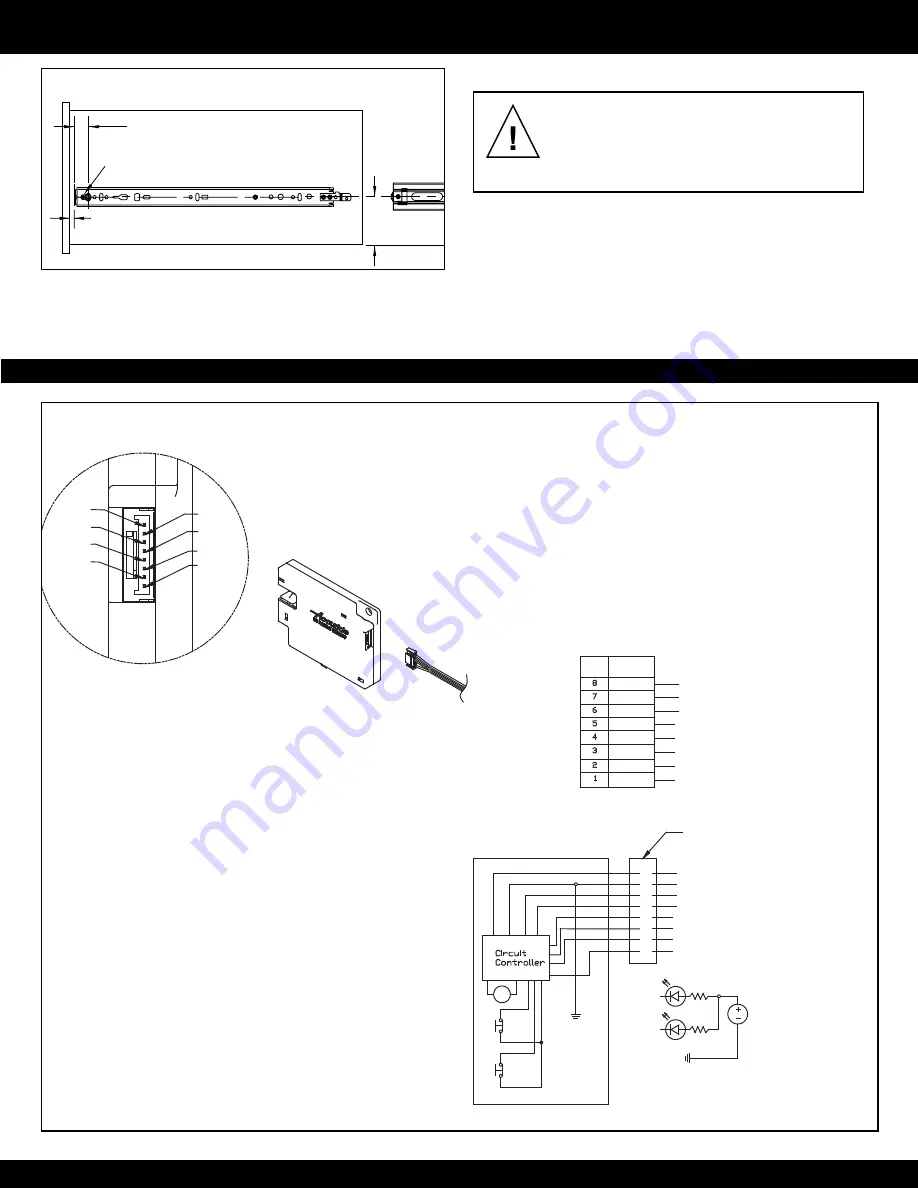
11/16" [17.8]
Drawer Member Setback
1/8" for Conventional Mounting
[5.2] for 32 mm Mounting
Cam Adjustment
1/4" [6.4]
1 1/4" [31.8]
3
Figure 5.
Drawer Insertion and Adjustment
WARNING!
Before installing the drawer, you must
have access to the lock’s manual override lever
or the activation device must be connected and
working properly. Otherwise, you will not be able to
unlock the slide and open the drawer.
1. Make sure the ball bearing retainers in the cabinet are fully
forward. Install drawer into cabinet and close the drawer.
2. Install additional screws to secure.
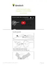
WIRING SCHEMATIC
PIN 8
PIN 7
PIN 6
PIN 5
PIN 4
PIN 3
PIN 2
PIN 1
Jumper connection for TR only
Lock Status
PWR (+5VDC to +24VDC Max)
PWR (-) Ground
Trigger : See Note 3
WIRE
COLOR
RED
GREY
GREY
GREY
GREY
GREY
GREY
GREY
Drawer Status
For internal use only, do not use*
For internal use only, do not use*
M
P
W
R
(+
VD
C
)
P
W
R
(-
)
TR
IG
G
ER
8
7
4
3
2
1
Drawer Status
6
5
Jumper connection for TR only
“DC”
“LC”
PWR (+5VDC to +24VDC)
PWR (-) Ground
Trigger : See Note 3
For internal use only, do not use*
For internal use only, do not use*
Lock Status
Technical Data
Voltage Supply :
+5VDC to +24VDC Maximum
Current Consumption :
50mA for 200 milliseconds @12VDC
(Unlocking and Locking)
Internal Sensor Specifications
Mechanical Life : 300,000 cycles
(Drawer Contact "DC")
(Lock Contact "LC")
Notes:
1. Drawer status output:
Drawer open : = “Open”
Drawer closed : = “Ground”
2. Lock status output:
Lock is unlocked : = “Open”
Lock is locked : = “Ground”
3. +5VDC to +24VDC Max at pin 6 will unlock
the Electronic Lock. The Electronic Lock will
remain unlocked until +VDC is removed.
4. (*) PIN 2 & 3 ARE USED FOR INTERNAL USE
DO NOT USE.
Pin 4
Pin 1
V (+5 to +24VDC)
example of drawer and lock status connection
using LED’s. Pin 4 & 1 maximum rating 30VDC@500mA
Pin 7
SM08B-GHS-TB
(JST lock connector)
GHR-08V-S
(JST cable connector)
OEM Cable
Connector
Conventional Mounting and 32 mm Mounting - Drawer
power Requirements and Connectors


