Accutech Wireless
Base Radio User Manual
6
Rev 1.56
Caution
Make sure only
ONE power supply
is routed to the Base Radio at any time!
(Does not apply to Loop Power Supplies)
!
!
The Accutech Base Radio is designed to use a 24 VDC power supply at a
minimum of 0.5 Amps. Accutech offers 110VAC/120VAC-15W DIN rail
mounted 24VDC converter for this purpose. For more information contact
your Accutech Representative.
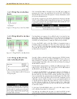
The Ground or Negative wire should be placed in the left most slot labeled
“GND” on the PCBoard of the terminal block in Figure 3.4. The Positive
wire should be placed in the same terminal block in the slot labeled “24V”
on the PCBoard as shown in Figure 3.4.
3.2.2: Wiring Power to the Base
Radio
Figure 3.4: Wiring Power to the Base Radio
3.2.3: Wiring RS-485 to the Base
Radio
The Base Radio also requires a 2 wire RS-485 cable to be wired for com-
munications. Wiring communications to a PC in order to run the Wireless
Instrumentation Manager (WIM) software requires the use of an RS-485
to RS-232 converter as most PC’s cannot be wired directly to RS-485.
To wire the RS-485 cable to the Base Radio we recommend using a
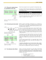
22AWG twisted pair shielded wire. Place one of the twisted pair wires in
the “A” (Tx+/Rx+) slot of the same terminal block as the power supply
wires, and the other wire in the “B” (Tx-/RX-) slot of the terminal block
as shown below in Figure 3.5.
Figure 3.5: Wiring RS-485 to the Base Radio
NOTE
The RS-485 communication setup is half duplex.
If the Base Radio in the application is wired to an
RS-485 to RS-232 converter, the A (Tx+/Rx+)
and B (Tx-/Rx-) wires may need to be crossed for
correct operation. Please see the converter’s user
manual for further instructions.
Accutech offers an optically isolated, surge protected, DIN Rail mount-
able B&B Electronics converter (Model 485LDRC9). Because there are
many RS-485/232 Converters available, please see your converters in-
struction manual for details as this section will only discuss the wiring of
the 485LDRC9 converter.
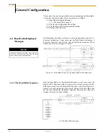
The Base Radio communicated via a half-duplex differential signal with A
being Tx+/Rx+ and B being Tx-/Rx-. To properly wire the Base Radio to
the 485LDRC9, you should follow Figure 3.6.
To configure the 485LDRC9 to the appropriate baud rate (38.4Kbaud), as
set of dip switches must be configured. These switches can be found on
the side of the converter. The first four switches should be in the ON posi-
tion to indicate that the communications are half duplex. The fifth switch
should also be in the ON position as this activates the termination resistor
within the converter. Finally, switches six, seven, and eight should be set
to the OFF position to indicate the correct baud rate. (Note: An 8.2K resis-
tor (R11) has been installed at the factory to achieve these higher baud
rates. If you did not purchase the converter from the factory you will need
to install this resistor).
To wire power to the 485LDRC9, place a +10 to 30 VDC supply to termi-
nal F, and place the ground (V-) to terminal C.
The final step in installing the converter is to attach an RS-232 (serial)
cable from the converter to an available serial port on your computer.
Figure 3.6: Base Radio to RS-232 Converter
Wiring Diagram
3.2.4: Wiring an RS-232 Con-
verter to the Base Radio
Summary of Contents for WI-BR-I-XP
Page 2: ......
Page 4: ......
Page 30: ...Accutech Wireless Base Radio User Manual 24 Rev 1 56 Base Radio Menu Map Appendix B...
Page 31: ......

