Accutech Wireless
Base Radio User Manual
16
Rev 1.56
6.3.1.1.3: Base Radio On/Offline
Field Unit Registers
On the left are the values for the Online/Offline Status of Field Units 1-16
holding register in the Base Radio. The other online/offline status holding
registers hold the status of the remaining Field Units with RF IDs 17
through 50.
Value
Field Unit Device Status
1 Field Unit 1 Online Status
2 Field Unit 2 Online Status
4 Field Unit 3 Online Status
8 Field Unit 4 Online Status
16 Field Unit 5 Online Status
32 Field Unit 6 Online Status
64 Field Unit 7 Online Status
127 Field Unit 8 Online Status
256 Field Unit 9 Online Status
512 Field Unit 10 Online Status
1024 Field Unit 11 Online Status
2048 Field Unit 12 Online Status
4096 Field Unit 13 Online Status
8192 Field Unit 14 Online Status
16384 Field Unit 15 Online Status
32768 Field Unit 16 Online Status
To decode the status register, take the value of the register and subtract the
largest value listed in the table above that does not cause the result to be
negative. Take the resulting total from the subtraction and subtract the
next largest number possible and so on until the result is zero. Each value
that was used in the subtraction indicates that the Field Unit is online.
For example: The On/Offline Status holding register contains the value 15.
In this case the largest value we can subtract is 8, which leaves a result of
7. Now we can subtract 4 from 7 and get 3. Now subtract 2 from 3 and we
get 1. Finally we subtract 1 from 1 and get 0, so we are done. Which Field
Units are online? We subtracted 8,4,2 and 1, and these numbers corre-
spond to Field Units’ with RF IDs 1,2,3 and 4.
In another example, say the On/Offline Status holding register contains the
value 6. We can subtract 4 to get 2. Then we can subtract 2 to get 0. Thus
Field Unit 2 and 3 are online, but Field Units 1 and 4 are offline.
6.3.1.2: Field Unit Holding
Registers
The following are the Field Unit holding registers when used in the
Device
ID Mapping Mode
(First Table) and the
Register Mapping Mode
(Second Table).
Field Unit Holding Registers
(DEVMODE Only)
Device ID
=
Base Radio Modbus ID + RF ID
Register Address
Description
Register Type
00001 Device
Type
32-Bit
IEEE
Floating Point
00002 Device
Type
00003 Device
Status
32-Bit
IEEE
Floating Point
00004 Device
Status
00005 Primary Sensor Value
32-Bit IEEE
Floating Point
00006 Primary
Sensor
Value
00007 Secondary Sensor Value
32-Bit IEEE
Floating Point
00008 Secondary Sensor Value
00009 Tertiary Sensor Value
32-Bit IEEE
Floating Point
00010 Tertiary
Sensor
Value
Field Unit Holding Registers
(REGMODE Only)
Device ID
=
Base Radio Modbus ID
Register Address
Description
Register Type
00001 + (RF ID * 10) Device Type
32-Bit IEEE
Floating Point
00002 + (RF ID * 10) Device Type
00003 + (RF ID * 10) Device Status
32-Bit IEEE
Floating Point
00004 + (RF ID * 10) Device Status
00005 + (RF ID * 10) Primary Sensor Value
32-Bit IEEE
Floating Point
00006 + (RF ID * 10) Primary Sensor Value
00007 + (RF ID * 10) Secondary Sensor Value
32-Bit IEEE
Floating Point
00008 + (RF ID * 10) Secondary Sensor Value
00009 + (RF ID * 10) Tertiary Sensor Value
32-Bit IEEE
Floating Point
00010+ (RF ID * 10) Tertiary Sensor Value
NOTE
If you have purchased any
Wireless
Differential Pres-
sure Field Units
, please see
the User Manual for spe-
cific Modbus holding regis-
ter differences from those
listed in the following sec-
Summary of Contents for WI-BR-I-XP
Page 2: ......
Page 4: ......
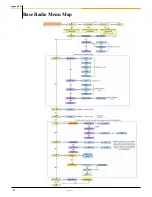
Page 30: ...Accutech Wireless Base Radio User Manual 24 Rev 1 56 Base Radio Menu Map Appendix B...
Page 31: ......

