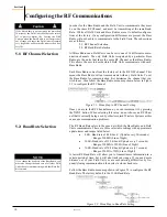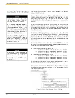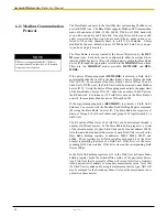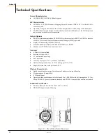
Accutech Wireless
Base Radio User Manual
20
Rev 1.56
Configuring the Analog Output Loop
Section 7
The following sections only apply if you have purchased the Analog Out-
put option.
If you have ordered the Analog Output (AO) option for the Base Radio
then the single 4-20mA analog output loop on the Base Radio has been
enabled, and the following menu options are available in the Base Radio to
support the configuration of this option. The subsections are as follows:
7.1: Trimming the Output Loop
7.2: Selecting the Failsafe Output
7.3: Selecting Which Field Unit is Output
7.1: Trimming the Output Loop
The Trim menu function on the Base Radio allows the user to increase or
decrease the 4mA and 20mA outputs of the Base Radio analog output loop
to match the user’s existing system. For example, if the Base Radio is out-
putting 4mA, but the user’s system is indicating the Base Radio is only
outputting 3.85mA, then the user would enter a +0.15mA in the 4mA trim
menu, which would in turn match the Base Radio 4mA output to the user’s
existing system.
To output the 4mA and 20mA from the Base Radio for measurement at the
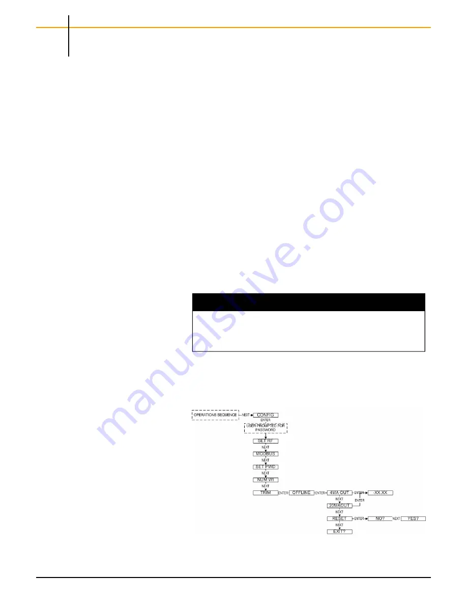
existing system follow the menu map in Figure 7.1 until the 4mA OUT is
displayed on the Base Radio LCD.
The user can then make corrective adjustments to this value by pressing
the ENTER button and adding or subtracting to the current value. Pressing
ENTER will then save and output the adjusted value. The 20mA output is
set up in the same fashion.
NOTE
The OFFLINE screen indicates that the analog output has been disabled,
and you should now take the PLC/DCS offline for this unit. While the
4MA OUT is being displayed on the LCD the analog output loop will be
outputting 4mA to the existing system.
Figure 7.1: Menu Map to the Trim Function
Summary of Contents for WI-BR-I-XP
Page 2: ......
Page 4: ......
Page 30: ...Accutech Wireless Base Radio User Manual 24 Rev 1 56 Base Radio Menu Map Appendix B...
Page 31: ......

