background image

2-3. Schließen Sie den Wechselstrom-Abnehmer an den Wechselstromausgang des 

Wechselrichters an. 

Das Erdungskabel des Wechselstromausgangs sollte mit dem Erdungspunkt der 

angeschlossenen Geräte Kontakt bekommen. Dieses kann z.B. über eine 

Erdungsverteilerschiene oder einen Erdungsstab erfolgen.

ACHTUNG: 

Es besteht die Gefahr eines Stromschlags! Stecken Sie den Wechselstromstecker 

niemals dran oder weg, wenn der Hauptschalter des Wechselrichters auf EIN 

(“ON”) steht. 

2-4. Masse-Erdung: Verwenden Sie zur Erdung ein 2,5 mm

2

 starkes Kabel.

ACHTUNG: 

Die Inbetriebnahme des Wechselrichters ohne korrekte Erdung kann einen 

Stromschlag zur Folge haben. 

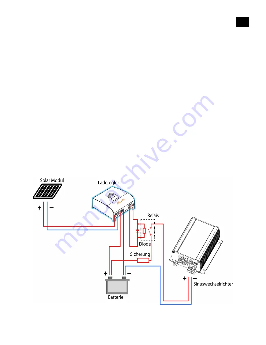
2-5. Anschluss des Wechselrichters an eine PV-Anlage:

Sollte die Verwendung der Tiefentladeschutz-Kreises eines Ladereglers erforderlich sein, ist 

ein Hilfsrelais (mit ausreichender Spulenspannung /Systemspannung) mit der 

entsprecheneden Nennstromleistung (vgl. die im Abschnitt „Installierung“ empfohlenen 

Richtwerte für Sicherungseinsätze) einzubauen. Die Relaisspule wird von dem Laderegler 

gesteuert/betrieben, und die Schaltkontakte kontrollieren die Verbindung zwischen 

Wechselrichter und Batterie. Da es sich bei der Relaisspule um eine induktive Last handelt, 

sollten Sie immer mit einer herkömmlichen Gleichrichterdiode (1A, 200 V Nennleistung) 

parallel zu der Relaisspule versehen werden (siehe Abbildung unten). 

11

DEU

Schaltplan für eine PV-Anlage mit Laderegler

All manuals and user guides at all-guides.com

Summary of Contents for SI 1500 Series

Page 1: ...ies Sinuswechselrichter Pure Sine Wave Inverter Inversor de ondas senoidales puras Convertisseur sinusoïdal pur Inversor de Onda Senoidal Pura 正弦波逆变器 All manuals and user guides at all guides com a l l g u i d e s c o m ...

Page 2: ...CONTENTS 1 14 15 27 28 40 41 53 54 66 67 78 Bedienungsanleitung User Manual Manual de Instrucciones Guide de l utilisateur Manual do Usuario 用户说明书 All manuals and user guides at all guides com ...

Page 3: ...en 3 2 Leistungsdaten 4 3 Beschreibung der Benutzerplattform 5 3 1 Vorderseite 5 3 2 Rückseite 7 Installierung und Bedienungshinweise 9 1 Standort 9 2 Installierung 9 3 Inbetriebnahme 12 Schutz und Fehlerbehebung 12 1 Niedrige Batteriespannung 12 2 Hohe Batteriespannung 12 3 Schutz vor Überlast und Kurzschluss 13 4 Schutz vor Übertemperatur 13 Wartung 14 Garantie 14 1 DEU All manuals and user guid...

Page 4: ...en gelagert werden oder in einer Umgebung in der ein Zündschutz erforderlich ist Das gilt für sämtliche Räume mit benzinbetriebenen Maschinen Kraftstofftanks oder Füge bzw Anschlussstellen zwischen Bestandteilen eines Kraftstoffsystems 2 Vorsichtsmaßnahmen im Umgang mit Batterien Wenn Batteriesäure mit Ihrer Haut oder Ihrer Kleidung in Berührung kommen sollte so müssen Sie sie sofort mit Seife abw...

Page 5: ...g von Gleich in Wechselstrom Er zeichnet sich aus durch eine Reihe hervorragender technischer Eigenschaften u a Reiner Sinuswellenausgang THD 3 Ausgangsfrequenz 50 60 Hz per Schalter einstellbar Energiesparmodus wählbar Konstruktion mit vollkommen isoliertem Eingang und Ausgang Hoher Wirkungsgrad Verträgt hohe induktive und kapazitive Belastung im Einschaltmoment Zweifarbige LED Anzeige des Betrie...

Page 6: ...VDC Wirkungsgrad Volllast 91 92 93 94 Leerlaufstromverbrauch 0 75 A 0 4 A 0 7 A 0 4 A Bereitschaftsstromverbrauch 0 15 A 0 09 A 0 15 A 0 09 A Schutzschaltung Überlast Kurzschluss Über Unter Eingangsspannung Übertemperatur Betriebstemperatur 20 C 40 C Lagertemperatur 30 C 70 C Maximale Luftfeuchtigkeit 90 nichtkondensierend Sicherheitsstandards FCC Class A EN55022 1997 EN55024 1997 EN61000 3 2 1998...

Page 7: ...0 Hz für SI1500 12110 1 0 SI1500 24110 1 0 und SI1500 48110 1 0 Der Energiesparmodus ist einstellbar für S1 S2 und S3 bei niedrigeren Lasten als angegeben springt das Gerät zum Energiesparmodus um DIP Schalter S1 DIP Schalter S2 DIP Schalter S3 Energiesparmodus AUS AUS AUS Energiesparmodus aus EIN AUS AUS 20 W AUS EIN AUS 40 W EIN EIN AUS 55 W AUS AUS EIN 75 W EIN AUS EIN 95 W AUS EIN EIN 115 W EI...

Page 8: ...0 495W 495 1125W 1125 1450W 1450W 1500W Status Anzeige 1 LED Anzeige normaler Betrieb 2 Rotes Aufleuchten mit schnell blinkender Eingangsspannungs Anzeige zeigt an dass die Wechselspannung wegen abnormaler Spannung abgeschaltet ist schnelleres Blinken zeigt Überspannungschutz an langsameres Blinken zeigt Niederspannungsschutz an 3 Grünes langsames Blinken zeigt Betriebsbereitschaft an 4 Rot zeigt ...

Page 9: ...rungseinheit angeschlossen werden GND ENB Anschluss Bildet den Anschluss für die Fernbedienung mit der der Wechselrichter an oder ausgeschaltet werden kann Der Schalter kann wie folgt eingestellt werden 4 Modi es kann aber nur ein Modus zu jeder Zeit eingestellt werden Modus 1 Modus 2 Die Transistor Vceo sollte grösser als die max Batteriespannung sein 7 DEU An Wechselrichter An Aus Wechselrichter...

Page 10: ...2 5 cm einzuhalten Der Lüfter ist last 53 5 bzw temperaturkontrolliert 55 5 C Masseanschluss Wird bei dem Wechselrichter zum Anschluss an einen Erdungsstab verwendet 8 DEU Externe Quellle An Wechselrichter An Aus Wechselrichter Aus All manuals and user guides at all guides com ...

Page 11: ...den Wechselrichter nicht in einer staubigen Umgebung Staubteilchen können in das Gerät gesaugt werden wenn der Belüfter in Betrieb ist Von Batterien fernhalten Installieren Sie den Wechselrichter nicht an einem Ort wo er korrosiven Gasen ausgesetzt ist die von Batterien erzeugt werden 2 Installierung 2 1 Vor der Installierung des Wechselrichters muss der Hauptschalter in der AUS off Position stehe...

Page 12: ...230 50 ACHTUNG Der Anschluss mit umgekehrter Polarität kann ohne externen Sicherungsschutz zur Beschädigung des Wechselrichters führen ACHTUNG ACHTUNG Sorgen Sie dafür dass die Anschlüsse in gutem Zustand sind da es sonst zu Übertemperatur und Bränden kommen könnte ACHTUNG Die Sicherung muss am positiven Leiter angebracht werden Eine falsch angebrachte Sicherung kann den Wechselrichter beschädigen...

Page 13: ... zur Folge haben 2 5 Anschluss des Wechselrichters an eine PV Anlage Sollte die Verwendung der Tiefentladeschutz Kreises eines Ladereglers erforderlich sein ist ein Hilfsrelais mit ausreichender Spulenspannung Systemspannung mit der entsprecheneden Nennstromleistung vgl die im Abschnitt Installierung empfohlenen Richtwerte für Sicherungseinsätze einzubauen Die Relaisspule wird von dem Laderegler g...

Page 14: ...steuerung am Wechselrichter an Stellen Sie den Hauptschalter auf Fernsteuerungsbetrieb ein Stellen Sie den Fernsteuerungsschalter ON oder OFF um den Betrieb des Wechselrichters zu steuern Schutz und Fehlerbehebung 1 Niedrige Batteriespannung Alarm Schutz Signale Batteriespannung Fehlerbehebung Alarm Niederspannung Eingangsanzeige blinkt langsam Summer piept 21 2 42 0 V Batterie aufladen bzw Kabelv...

Page 15: ...ng wieder zu erstellen 4 Schutz vor Übertemperatur Alarm Schutz Signale Innentem peratur Fehlerbehebung Schutz vor Übertemperatur Statusanzeige leuchtet rot schnelles Blinken zweimal hintereinander alle 1 6 Sekunden 70 5 C Lüftung verbessern bzw Umgebungstemperatur reduzieren Wenn die Innentemperatur des Geräts auf unter 45 5 C geht nimmt der Wechselrichter seinen normalen Betrieb wieder auf ACHTU...

Page 16: ...icht unter diesen Garantieschutz Anschließen des Geräts an ungeeignete Stromquellen Betrieb mit Elektrogeräten mit zu hohem Stromverbrauch oder Benutzung in ungeeigneter Umgebung führen zu einem Verlust des Garantieschutzes Der Hersteller gibt dafür keine weitere Garantie Keine weiteren Garantien insbesondere Garantien allgemeiner oder besonderer Gebrauchstauglichkeit sind ausdrücklich oder stills...

Page 17: ...formance 17 3 User Interface Overview 18 3 1 Front Panel Components 18 3 2 Rear Panel Components 20 Installation and user instructions 22 1 Where to install 22 2 Installation 22 3 Operation 25 Protection and troubleshooting 25 1 Battery low voltage 25 2 Battery high voltage 25 3 Over load and short circuit protections 26 4 Over temperature protection 26 Maintenance 27 Warranty 27 15 ENG All manual...

Page 18: ...s with running cold water for at least 20 minutes and get medical attention immediately Never smoke or allow sparks or flame in vicinity of battery or engine Do not drop metal tools on the battery The resulting spark or short circuit on the battery or other electrical part may cause explosion Remove personal metal items such as rings bracelets necklaces and watches when working with a lead acid ba...

Page 19: ...Hz 0 1 Input Voltage 24 Vdc 48 Vdc 24 Vdc 48 Vdc Input Voltage Range 21 0 31 0 Vdc 42 0 60 0 Vdc 21 0 31 0 Vdc 42 0 60 0 Vdc Efficiency max 91 92 93 94 No load power consumption 0 75 A 0 4 A 0 7 A 0 4 A Standby power consumption 0 15 A 0 09 A 0 15 A 0 09 A Protections Overload short circuit DC over under voltage over Temperature Operating Temp 20 C 40 C Storage Temp 30 C 70 C WorkingHumidity Max 9...

Page 20: ... and SI1500 48230 1 0 60Hz for SI1500 12110 1 0 SI1500 24110 1 0 and SI1500 48110 1 0 Power Saving Mode PSM is adjustable and can be set by means of S1 S2 and S3 loads smaller than indicated will lead to PSM DIP Switch S1 DIP Switch S2 DIP Switch S3 Power Saving OFF OFF OFF Power saving mode off ON OFF OFF 20 W OFF ON OFF 40 W ON ON OFF 55 W OFF OFF ON 75 W ON OFF ON 95 W OFF ON ON 115 W ON ON ON ...

Page 21: ...zzer SI1500 0 120W 120 495W 495 1125W 1125 1450W 1450W 1500W Status Led 1 LED green normal operation 2 Red flash with the Input Level Led quickly blinking means AC off for abnormal voltage faster indicates over voltage protect and slower indicates low voltage protect 3 Green slow flashing indicates standby 4 Red indicates over Load protect 5 Red intermittent blinking means over temperature protect...

Page 22: ...he remote port is used to connect the remote control unit GND ENB Port The port is the connector for remote control switch which can turn the inverter on or off The switch can be set in following ways four modes total but you can only choose one at a time Mode 1 Mode 2 The transistor Vceo should be larger than max battery voltage Mode 3 20 ENG All manuals and user guides at all guides com ...

Page 23: ...istant from the nearby surroundings The fan is controlled according to loading 53 5 or temperature 55 5 Chassis Ground terminal It is used to connect the case of the inverter to a Grounding Rod or Bar 21 ENG All manuals and user guides at all guides com ...

Page 24: ...d Dust Do not install the Inverter in dusty environments This dust can be pulled into the unit when the cooling fan is operating Away from batteries Do not mount the Inverter where it will be exposed to corrosive gases produced by batteries 2 Installation 2 1 Before installing the inverter make sure the main switch is in OFF position 2 2 DC Input connection We recommend the DC cable length should ...

Page 25: ...use A SI1500 24110 24230 100 SI1500 48110 48230 50 WARNING Wrong polarity connection may damage the inverters without the external fuse protection WARNING Make sure the connections are very well made or overheating and fire may occur WARNING The installation of a fuse must be on the positive conductor Otherwise it may cause damage to the inverter and will void the warranty 23 ENG All manuals and u...

Page 26: ...OD Should there be a requirement to use the Low Voltage Disconnect levels of a charge controller than an auxiliary Relay with adequate coil voltage system voltage with the proper current rating for the inverter size refer to the fuse size we indicate in the Installation section has to be added to the system The relay coil will be controlled powered by the charge controller and the relay contacts w...

Page 27: ...switch to remote control position Turn the remote switch on or off to control the inverter operation or not Protection and troubleshooting 1 Battery low voltage Alarm protection Signals Battery voltage Trouble shooting Low voltage alarm Input level Led flashing slowly buzzer beeps 21 2 42 0 V Charge battery or check the conductor connection Low voltage shut down Input Level Led and status led beco...

Page 28: ...tput 4 Over temperature protection Alarm protection Signals Interior Temperature Trouble shooting Over temperature protection Status LED red flashing quickly twice every 1 6 seconds 70 5 Improve the ventilation or reduce the ambient temperature When the inverter interior temperature returns below 45 5 the inverter resumes normal operation WARNING Do not open or disassemble the Inverter Attempting ...

Page 29: ...does not cover damage arising from improper use such as plugging Connecting the unit into an unsuitable power sources and attempting to operate products with excessive power consumption requirements or use in unsuitable environments will result in loss of warranty This is the only warranty that the company makes No other warranties express or imply including warranties of merchantability and fitne...

Page 30: ...la interfaz de usuario 31 3 1 Componentes del panel frontal 31 3 2 Componentes del panel posterior 33 Instrucciones de instalación y para el usuario 35 1 Dónde instalar 35 2 Instalación 35 3 Funcionamiento 38 Protección y resolución de problemas 38 1 Bajo voltaje de la batería 38 2 Alto voltaje de la batería 38 3 Protecciones contra sobrecarga y cortocircuito 39 4 Protección contra exceso de tempe...

Page 31: ...acto con la piel o la ropa lave inmediatamente con jabón y enjuague con agua Si el ácido entra en los ojos enjuague los ojos inmediatamente con agua corriente fría durante al menos 20 minutos y consulte inmediatamente al médico Nunca fume ni permita que se generen chispas o llamas cerca de la batería o del motor No deje caer herramientas de metal sobre la batería La chispa o el cortocircuito que s...

Page 32: ...110 SI1500 24230 SI1500 48230 Voltaje de salida 110 Vac 5 230 Vac 5 Potencia nominal 1500 W Potencia pico 1650 1750W 180 s 1750 3000W 6 s Forma de la onda Onda senoidal pura DAT 3 de la carga lineal Frecuencia 50 60 Hz 0 1 Voltaje de entrada 24 Vdc 48 Vdc 24 Vdc 48 Vdc Rango de voltaje de entrada 21 0 31 0Vdc 42 0 60 0Vdc 21 0 31 0Vdc 42 0 60 0 Vdc Eficiencia máx 91 92 93 94 Consumo sin carga 0 75...

Page 33: ...1500 48110 1 0 El modo de ahorro de energía Power Saving Mode PSW es ajustable y se puede establecer por medio de S1 S2 y S3 las cargas menores a las indicadas conducen al modo de suministro de energía PSM Interruptor DIP S1 Interruptor DIP S2 Interruptor DIP S3 Ahorro de energía APAGADO APAGADO APAGADO Modo de ahorro de energía apagado ENCENDIDO APAGADO APAGADO 20 W APAGADO ENCENDIDO APAGADO 40 W...

Page 34: ...rma SI1500 0 120W 120 495W 495 1125W 1125 1450W 1450W 1500W LED de estado 1 LED verde funcionamiento normal 2 Destello rojo con el LED de nivel de entrada parpadeando con rapidez significa CA apagada por voltaje anormal mayor rapidez indica protección de sobrevoltaje y menor velocidad indica desconexión por bajo voltaje 3 Verde con destello lento indica en espera 4 Rojo indica protección contra so...

Page 35: ... puerto remoto se usa para conectar la unidad de control remoto opzional 24V Puerto GND ENB Este puerto es utilizado para conexión del interruptor remoto que enciende o apaga el inversor Instrucciones de instalación y para el usuario Modo 1 Modo 2 El voltaje Vceo especificada para o transistor deberá superior à máxima voltaje de Batería 33 ESP Inversor ativado Inversor apagado Inversor ativado Inv...

Page 36: ...olado en función de la carga 53 5 o la temperatura 55 5 Terminal de masa del chasis Se utiliza para conectar la caja de inversor a un vástago o jabalina de puesta a tierra 34 ESP Inversor ativado Inversor apagado Fonte externa de energia All manuals and user guides at all guides com a l l g u i d e s c o m ...

Page 37: ...egúrese de que las aberturas de ventilación en el frente y la parte posterior de la unidad no estén obstruidas Polvo no instale el inversor en ambientes con polvo Es posible que el polvo se succione hacia el interior de la unidad cuando funciona el ventilador Lejos de las baterías no instale el inversor donde pueda quedar expuesto a los gases corrosivos producidos por las baterías 2 Instalación 2 ...

Page 38: ...omendados consulte la tabla siguiente Modelo Nº Fusible A SI1500 24110 24230 100 SI1500 48110 48230 50 ADVERTENCIA La conexión con las polaridades cambiadas puede dañar el inversor si no tiene un fusible externo de protección ADVERTENCIA Asegúrese de que las conexiones estén bien hechas para evitar riesgos de sobrecalentamiento e incendios ADVERTENCIA La instalación del fusible se debe realizar en...

Page 39: ...ma fotovoltaico Si es necesario usar los niveles de desconexión por bajo voltaje de un controlador de carga un relé auxiliar con el adecuado voltaje de la bobina voltaje del sistema con la corriente nominal adecuada para el tamaño del inversor consulte el tamaño del fusible indicado en la sección de instalación debe ser añadido al sistema La bobina del relé se controla alimenta por medio del contr...

Page 40: ...remoto para controlar el funcionamiento del inversor Protección y resolución de problemas 1 Bajo voltaje de la batería Alarma protección Señales Voltaje de la batería Resolución de problemas Alarma de bajo voltaje LED de nivel de entrada destella despacio alarma suena 21 2 42 0 V Cargue la batería o verifique la conexión del conductor Desconexión por bajo voltaje LED de nivel de entrada y LED de e...

Page 41: ... CA 4 Protección contra exceso de temperatura Alarma protección Señales Temperatura interior Resolución de problemas Protección contra exceso de temperatura LED de estado rojo con destellos rápidos dos veces cada 1 6 segundos 70 5 Mejore la ventilación o reduzca la temperatura ambiente Cuando la temperatura interior del inversor vuelve a bajar a 45 5 el inversor reanuda el funcionamiento normal AD...

Page 42: ... los daños generados por uso inadecuado tal como obstrucción La conexión de la unidad a fuentes de alimentación inadecuadas y el intento de hacer funcionar los productos con excesivos requisitos de consumo de energía o el uso en entornos inapropiados tendrán como consecuencia la pérdida de la garantía Esta es la única garantía que ofrece la empresa Ninguna otra garantía expresa o implícita incluye...

Page 43: ... Vue d ensemble de l interface utilisateur 44 3 1 Éléments du panneau avant 44 3 2 Éléments du panneau arrière 46 Instructions d installation et d utilisation 48 1 Où installer 48 2 Installation 48 3 Fonctionnement 51 Protection et dépannage 51 1 Tension de la batterie faible 51 2 Tension de batterie élevée 51 3 Protections contre les surcharges et les court circuits 52 4 Protection contre la surc...

Page 44: ... l acide de la batterie et la peau ou les vêtements nettoyer immédiatement avec du savon et rincer à l eau Si de l acide pénètre dans les yeux rincer immédiatement les yeux à l eau froide pendant 20 minutes au moins et consulter immédiatement un médecin Ne pas fumer ou approcher d étincelles ou de flammes au voisinage de la batterie ou du moteur Ne pas laisser tomber d outils métalliques sur la ba...

Page 45: ...on de sortie 110 Vac 5 230 Vac 5 Puissance nominale 1500 W Puissance maximale ou en crête 1650 1750 W 180 s 1750 3000 W 6 s Forme d onde Onde sinusoïdale THD 3 sur charge linéaire Fréquence 50 60 Hz 0 1 Tension d entrée 24 Vdc 48 Vdc 24 Vdc 48 Vdc Tension d entrée admissible 21 0 31 0Vdc 42 0 60 0Vdc 21 0 31 0Vdc 42 0 60 0 Vdc Efficacité max 91 92 93 94 Consommation électrique à vide 0 75 A 0 4 A ...

Page 46: ...t SI1500 48110 1 0 Le mode économie d énergie PSW est modifiable et peut être réglé au moyen des S1 S2 et S3 les charges plus petites qu indiquées provoqueront le passage en mode économie d énergie Interrupteur DIP S1 Interrupteur DIP S2 Interrupteur DIP S3 Économie d énergie ARRÊT ARRÊT ARRÊT mode économie d énergie off MARCHE ARRÊT ARRÊT 20 W ARRÊT MARCHE ARRÊT 40 W MARCHE MARCHE ARRÊT 55 W ARRÊ...

Page 47: ...495 1125W 1125 1450W 1450W 1500W État du voyant LED 1 LED verte fonctionnement normal 2 La LED d entrée clignotant rapidement en rouge signifie la coupure de la sortie CA pour tension anormale un clignotement plus rapide indiquant une surtension et un clignotement plus lent indiquant une sous tension 3 Le clignotement vert lent signifie la mise en veille 4 Rouge pour protection contre les surcharg...

Page 48: ...pour raccorder une unité de commande à distance Circuit GND ENB Prévoit le circuit pour télécommande à travers que cela peut être lié ou et a marché ou arrêt Ce changement peut être connecté dans 4 chemins différents mais seulement une modalité à un chaque fois Mode 1 Mode 2 La voltage spécifié Vceo pour le transistor faut plus haut que le plus haut voltage de la batterie 46 FRA Convertisseur marc...

Page 49: ...eur est commandé par la charge d utilisation 53 5 ou par la température 55 5 C Borne de mise à la terre du châssis Elle est utilisée pour raccorder le boîtier du convertisseur à une ligne barre de terre 47 FRA Convertisseur marche Convertisseur arrêt Source externe d énergie All manuals and user guides at all guides com ...

Page 50: ...és Non poussiéreux Ne pas installer le convertisseur dans un environnement poussiéreux La poussière pourrait pénétrer dans l unité lorsque le ventilateur est en marche Éloigné de batteries Ne pas placer le convertisseur dans un endroit exposé aux émanations de gaz corrosifs de batteries 2 Installation 2 1 Avant d installer le convertisseur assurez vous que l interrupteur principal est en position ...

Page 51: ...0 24110 24230 100 SI1500 48110 48230 50 ATTENTION Le non respect des polarités peut endommager les convertisseurs ne disposant pas de fusible externe ATTENTION S assurer que les branchements sont correctement effectués afin d éviter tout risque de surchauffe ou d incendie ATTENTION La pose du fusible doit se faire sur le pôle positif Dans le cas contraire le convertisseur pourrait être endommagé e...

Page 52: ...as où il serait nécessaire d utiliser les niveaux de déconnexion de faible tension d un contrôleur de charge un relais auxiliaire avec la tension bobine système adéquate délivrant un courant nominal correspondant à la capacité du convertisseur se référer au calibre de fusible indiqué au paragraphe Installation doit être ajouté au système La bobine relais sera commandée alimentée par le contrôleur ...

Page 53: ...F Relier la commande à distance au convertisseur Placer l interrupteur principal en position commande à distance Placer l interrupteur à distance sur Marche ON ou Arrêt OFF pour commander le fonctionnement ou non du convertisseur Protection et dépannage 1 Tension de la batterie faible Alarme protection Signaux Tension de batterie Dépannage Alarme tension faible Led d entrée clignotant lentement av...

Page 54: ...z le convertisseur hors tension puis replacez le sous tension pour reconnecter lasortie AC 4 Protection contre la surchauffe Alarme protection Signaux Températur e intérieure Dépannage Protection contre la surchauffe Led d état rouge clignotant rapidement deux fois toutes les 1 6 s 70 5 Améliorer l aération ou réduire la température ambiante Lorsque la température intérieure du convertisseur redes...

Page 55: ...ausés par une utilisation non appropriée telle que l enfichage Le branchement de l unité à une source d alimentation inadaptée et le fonctionnement de produits nécessitant une alimentation excessive ou l utilisation dans un environnement inadapté entraîneront l annulation de la garantie Ceci est l unique garantie assurée par l entreprise Il n existe aucune autre garantie explicite ou implicite y c...

Page 56: ...a interface do usuário 57 3 1 Componentes do painel frontal 57 3 2 Componentes do painel traseiro 59 Instalação e instruções de uso 61 1 Onde instalar 61 2 Instalação 61 3 Operação 64 Proteção e solução de problemas 64 1 Baixa tensão da bateria 64 2 Tensão elevada da bateria 65 3 Proteções contra sobrecarga e curto circuito 65 4 Proteções contra so sobreaquecimento 65 Manutenção 66 Garantia 66 54 ...

Page 57: ...com sabão e enxague com água Se o ácido penetrarn os olhos lave os imediatamente com água corrente fria por pelo menos 20 minutos e procure atendimento médico imediatamente Nunca fume produza faíscas ou chamas nas proximidades da bateria ou do inversor Não deixe cair ferramentas de metal na bateria A faísca ou curto circuito produzidos por outro elemento condutor na bateria podem causar explosão R...

Page 58: ...ncia 1650 1750 W 180 s 1750 3000 W 6 s Forma de onda Onda senoidal pura DHT 3 carga linear Frequência 50 60 Hz 0 1 Tensão de entrada 24 Vcc 48 Vcc 24 Vcc 48 Vcc Variação da tensão de entrada 21 0 31 0 Vcc 42 0 60 0 Vcc 21 0 31 0 Vcc 42 0 60 0 Vcc Eficiência máx 91 92 93 94 Consumo de energia sem carga 0 75 A 0 4 A 0 7 A 0 4 A Consumo de energia em modo de espera 0 15 A 0 09 A 0 15 A 0 09 A Proteçõ...

Page 59: ...programável e pode ser configurado através das chaves DIP S1 S2 e S3 As cargas inferiores às indicadas também poderão ativar este modo Interruptor DIP S1 Interruptor DIP S2 Interruptor DIP S3 Economia de energia OFF DESLIGADO OFF DESLIGADO OFF DESLIGADO Modo economia de energia ON LIGADO OFF DESLIGADO OFF DESLIGADO 20 W OFF DESLIGADO ON LIGADO OFF DESLIGADO 40 W ON LIGADO ON LIGADO OFF DESLIGADO 5...

Page 60: ...ED OFF DESLIGADO Verde Laranja Vermelho Vermelho piscante Vermelho piscante alarme SI1500 0 120W 120 495W 495 1125W 1125 1450W 1450W 1500W Led de Status 1 LED verde operação normal 2 Led vermelho nível de entrada piscando rápidamente significa que a saida foi desligada devido à uma anormalidade de tensão Piscando rápidamente indica proteção contra sobretensão e mais lentamente indica proteção cont...

Page 61: ...anentes no inversor Porta remota A porta remota é usada para conectar a unidade de Controle Remoto Conexão GND ENB Permite a conexão para controle remoto através do qual este pode ser ligado ou desligado Este interruptor pode ser conectado de 4 formas diferentes mas somente uma modalidade a cada vez Modo 1 Modo 2 A tensão Vceo especificada para o transistor deverá ser superior à máxima tensão de b...

Page 62: ...controlado de acordo com a carga 53 5 ou temperatura 55 5 Terminal de aterramento do gabinete Usado para conectar o gabinete do inversor à uma haste ou barra de aterramento 60 POR Inversor ligado Inversor desligado Inversor ligado Inversor desligado Fonte externa de energia All manuals and user guides at all guides com ...

Page 63: ...o instalar o inversor em ambientes com poeira Esta poeira pode ser aspirada para dentro da unidade quando o ventilador estiver em funcionamento Longe de baterias Não instalar o inversor onde ele possa estar exposto a gases corrosivos do tipo produzidos por baterias 2 Instalação 2 1 Antes de instalar o inversor certifique se de que o interruptor principal esteja na posição desligado OFF 2 2 Conexão...

Page 64: ... 24230 100 SI1500 48110 48230 50 AVISO A conexão invertida da polaridade pode danificar os inversores na ausência de fusível externo AVISO Certifique se de que todas as conexões estejam bem feitas ou sobreaquecimento e incêndio poderão ocorrer AVISO A instalação de um fusível deve ser feita no condutor positivo Caso contrário poderão ocorrer danos ao inversor com perda da garantia 62 POR All manua...

Page 65: ...para desligamento por sub tensão da bateria LVD No caso de se desejar utilizar os niveis de sub tensão oferecidos por um controlador de carga para desligamento do inversor será necessário adicionar um relé auxiliar com capacidade de corrente nominal adequada ao tamanho do inversor confira o tamanho do fusível indicado na seção Instalação ao sistema A bobina do relé será controlada alimentada pelo ...

Page 66: ...r se desliga e o LED se apaga 3 3 Operação com controle remoto optional 24 V Verifique se o interruptor principal está na posição desligado OFF Conecte o controle remoto no inversor Ajuste o seletor para a posição controle remoto Ligue e desligue o interruptor remoto através das funções ligado ou desligado para testar o seu funcionamento atuação Proteção e solução de problemas 1 Baixa tensão da ba...

Page 67: ... Reduzir a carga Proteção contra sobrecarga ou curto circuito LED de estado sinaliza vermelho LED de nível de carga desligado Ao entrar nos estado modo de proteção desligue o inversor e em seguida ligue o novamente para reconectar à saída CA 4 Proteção contra sobreaquecimento Alarme proteção Sinais Temperatura Interior Solução de problemas Proteção contra sobreaquecimento LED de estado sinaliza ve...

Page 68: ...ão seja interna ou externa não cobrindo danos provenientes de uso impróprio como a má conexão por exemplo Conectar a unidade a uma fonte de alimentação inadequada e tentar operar produtos com exigências de consumo excessivo de energia ou o uso em ambientes inadequados irá resultar na perda da garantia Esta é a única garantia disponibilizada pela empresa Nenhuma outra garantia é válida incluindo ga...

Page 69: ...安全建议 68 2 蓄电池使用安全建议 68 产品介绍 68 1 特性 68 2 技术参数 69 3 面板介绍 70 3 1 前面板 70 3 2 后面板 72 安装说明 74 1 选择安装位置 74 2 安装 74 3 使用逆变器 77 保护功能和故障排除 77 1 蓄电池电压低 77 2 蓄电池电压过高 77 3 过载与短路保护 77 4 过温保护 78 保养 78 保修条款 78 67 中文 All manuals and user guides at all guides com ...

Page 70: ...即用清水和肥皂清洗 如果酸性物 质进入眼睛 应立即用循环的冷水清洗眼睛至少20分钟 并立即送医院治疗 杜绝一切烟 火花或火焰接近蓄电池和发动机 不要将金属类的工具放在电池上 这样很可能会在蓄电池上产生火花或短路并导致 其他电器设备爆炸 请摘掉耳环 手镯 项链 手表等金属饰品 蓄电池短路会产生很大的短路电流 可能会对人体造成严重烧伤 产品介绍 注意 逆变器启动时需要从低压直流电源 例如 蓄电池 获取很高的电流 因此在太阳 能系统中 我们强烈建议不要把逆变器直接连接在控制器的输出端 逆变器可以直接连 在蓄电池上 1 特性 正弦波逆变器采用目前最先进的直流变交流技术 它有许多卓越的特征 例如 纯正弦波输出 电阻性负载下总谐波失真 3 输出频率 50 60 Hz可选择 低功耗省电模式 显著提高系统效率并降低成本 输入 输出完全隔离 可满足多种应用需求 转换效率高 具备驱动感性负载和容性负载的能力 ...

Page 71: ...入电压范围 21 0 31 0 Vdc 42 0 60 0 Vdc 21 0 31 0 Vdc 42 0 60 0 Vdc 转换效率 91 92 93 94 自消耗电流 0 75 A 0 4 A 0 7 A 0 4 A 节电模式自消耗电流 0 15 A 0 09 A 0 15 A 0 09 A 保护模式 过压 欠压 短路 过温 过载 工作温度环境 20 C 40 C 储存温度范围 30 C 70 C 工作湿度环境 最大 90 非冷凝状态 安全标准 FCC Class A EN55022 1997 EN55024 1997 EN61000 3 2 1998 EN61000 3 3 1995 E mark e13 22876 Meet UL458 EN60950 1 冷却 制冷风扇自动控制 69 中文 All manuals and user guides at all guides com ...

Page 72: ...500 12110 1 0 SI1500 24110 1 0 和 SI1500 48110 1 0 为 60Hz 节电模式 PSM 由拨码开关 S1 S2 和 S3 设置 负载功率小于设定值 逆变器自动进入节 电模式 拨码开关 S1 拨码开关 S2 拨码开关 S3 负载功率 OFF 关 OFF 关 OFF 关 OFF ON 开 OFF 关 OFF 关 20 W 出厂设置 OFF 关 ON 开 OFF 关 40 W ON 开 ON 开 OFF 关 55 W OFF 关 OFF 关 ON 开 75 W ON 开 OFF 关 ON 开 95 W OFF 关 ON 开 ON 开 115 W ON 开 ON 开 ON 开 135W 70 中文 All manuals and user guides at all guides com ...

Page 73: ...9 0 49 8 56 8 橙色闪烁 29 0 30 0 56 8 59 2 红色闪烁 30 0 31 6 59 2 61 2 负载功率范围指示 LED灯状 态 关闭 绿色 橙色 红色 红色闪烁 红色闪烁 蜂鸣 输出功率 0 120W 120 495W 495 1125W 1125 1450W 1450W 1500W 逆变器工作状态指示 1 绿色 正常工作 2 红色和输入LED灯红色快闪 过压保护 红色和输入LED灯红色慢闪 欠压保护 3 绿色慢闪 待机状态 4 红色 过载保护 5 红色不连续闪烁 过温保护 交流输出插座 万能插座 散热通风口 不能阻塞散热器的通风口 要至少保持逆变器有30 mm的空气流动空间 71 中文 All manuals and user guides at all guides com ...

Page 74: ...能会烧毁逆变器内部的保险丝 严重情况可能会直接烧毁逆变器 外部控制连接端口 用于连接外部控制器 SI RSW 远程控制开关端口 用于连接远程控制开关 此开关能控制逆变器的启动或关闭 远程控制开关有以下4种 模式可选择 但同一时间只能选择使用一种模式 模式 1 模式 2 三极管基极与发射极之间的饱和电压Vceo 应大于蓄电池最高电压 72 中文 开关闭合 逆变器启动 开关打开 逆变器关闭 TR 闭合 逆变器启动 TR 打开 逆变器关闭 All manuals and user guides at all guides com ...

Page 75: ...模式 3 模式 4 风扇 不能阻塞逆变器的通风口 至少保持逆变器外有30 mm的空气流动空间 接地端 用于逆变器外壳接地 73 开关闭合 逆变器启动 开关打开 逆变器关闭 外部电源 中文 All manuals and user guides at all guides com ...

Page 76: ...何 遮挡或阻塞 灰尘 不能将逆变器安装在多灰尘的环境中 散热风扇工作时可能会把灰尘吸入逆 变器内部 这样会导致其不正常工作并且影响散热 隔离蓄电池 组 逆变器和蓄电池之间的电缆线不能过长 而且要将逆变器与蓄电 池隔离 推荐使用电缆的最大长度3 m 蓄电池所产生的气体具有强烈腐蚀性 长 时间会损坏逆变器 2 安装 2 1 在安装逆变器以前 请确认总开关在OFF 关闭 状态 2 2 蓄电池输入端的安装 使用电缆的长度不应长于1 8 m 推荐规格参见下表 型号 线缆截面积 SI1500 24110 24230 20 mm2 SI1500 48110 48230 12 mm2 线缆环形端子与逆变电源连接后 把固定螺栓拧紧 74 中文 All manuals and user guides at all guides com a l l g u i d e s c o m ...

Page 77: ...安装保险丝以保 护蓄电池 推荐规格请参见下表 逆变器型号 保险规格 SI1500 24110 24230 100 A SI1500 48110 48230 50 A 警告 决不允许蓄电池极性反接 这样可能会导致逆变器永久损坏 警告 请确保各个接线处牢固可靠 接线松动会导致电缆发热或产生火花而造成潜危险 警告 保险丝的安装务必正确 否则它可能造成逆变器的损坏 75 中文 All manuals and user guides at all guides com ...

Page 78: ... LVD 功能保护蓄电池避免其深度放电 因逆变器启动电流非常大 如果直接接到太阳能控制器的负载端 往往会造成控制器过 流保护或负载端损坏 因此逆变器是不允许直接接在太阳能控制器的负载端的 但是在 一些有逆变器的系统中 我们经常需要用到充放电控制器低压切断功能来保护蓄电池 采用下图的连接方式既可满足此类应用要求 继电器的工作电压和电流范围需要与控制 器和逆变器的电流范围 请参考本说明书指出的保险丝型号 相匹配 太阳能控制器控制 继电器线圈 继电器常开触点控制逆变器与电池连接或断开 因为继电器为感性负载 推荐与普通整流型1 A 200 V等级二极管并联使用 如下图 76 保险丝 带有控制器的光伏系统接线图 中文 All manuals and user guides at all guides com ...

Page 79: ...节外部控制器的开关ON 打开 或OFF 关闭 控制逆变器的启动和关闭 保护功能和故障排除 1 蓄电池电压低 报警 保护模式 状态指示 电池电压 故障排除 低压报警 蓄电池 LED 慢闪 蜂鸣器蜂鸣 21 2 42 0 V 检查蓄电池电压 或者连接状态 低压切断 蓄电池 LED 和状态 LED 红色且慢闪 20 6 41 2 V 当输入电压上升到25 6 51 2V 输出自动恢复 2 蓄电池电压过高 报警 保护模式 状态指示 电池电压 故障排除 高压报警 蓄电池 LED 快闪 29 0 56 8 V 检查蓄电池电压 高压切断 蓄电池 LED 和状态 LED 红色且快速闪烁 31 6 61 2 V 当输入电压下降到29 0 58 0 V 输出自动恢复 3 过载与短路保护 报警 保护模式 状态指示 故障排除 过载报警 负载 LED 闪烁 蜂鸣器蜂鸣 检查负载连接线路 或减少 负载 过载或短路保护...

Page 80: ...流输入端的螺丝 保修条款 本品如有材料部件或生产工艺缺陷 请将产品自费邮寄至我公司 我们将保证自购买日 期起 12 个月以内的免费保修 以下情况如因明显物理外力损毁 自主拆卸 或使用不当 而造成的产品问题 不在保修范围之内 用户在使用过程中如有电源连接不当 超负荷 运行 或者工作环境不符合产品要求而造成产品损坏 不在保修范围之内 此条款为我公司唯一保修条款 未设定以销售或其它目的的特殊保修条例 由于任何直 接或间接的原因导致产品损毁 我公司不承担免费保修义务 用户可选择有偿维修或更 换服务 如有更改 恕不另行通知 版本 20120406 在以下国家生产 德国 中国 玻利维亚 印度 Phocos AG 德国 www phocos com 78 ISO9001 RoHS 中文 All manuals and user guides at all guides com ...

Reviews: