background image


ACE088 

Page 2 of 21  

Rev Date: 9.21.2021


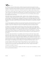
The information in this User’s Manual has been carefully reviewed and is believed to be accurate. The vendor 

assumes no responsibility for any inaccuracies that may be contained in this document and makes no commitment 
to update or to keep current the information in this manual, or to notify any person or organization of the updates. 
Please Note: For the most up-to-date version of this manual, please see our website at www.acecomputers.com. 


Ace Computers reserves the right to make changes to the product described in this manual at any time and without 
notice. This product, including software and documentation, is the property of Ace Computers and/ or its licensors, 
and is supplied only under a license. Any use or reproduction of this product is not allowed, except as expressly 
permitted by the terms of said license.  

IN NO EVENT WILL Ace Computers BE LIABLE FOR DIRECT, INDIRECT, SPECIAL, INCIDENTAL, SPECULATIVE OR 
CONSEQUENTIAL DAMAGES ARISING FROM THE USE OR INABILITY TO USE THIS PRODUCT OR DOCUMENTATION, 
EVEN IF ADVISED OF THE POSSIBILITY OF SUCH DAMAGES. IN PARTICULAR, SUPER MICRO COMPUTER, INC. SHALL 
NOT HAVE LIABILITY FOR ANY HARDWARE, SOFTWARE, OR DATA STORED OR USED WITH THE PRODUCT, INCLUDING 
THE COSTS OF REPAIRING, REPLACING, INTEGRATING, INSTALLING OR RECOVERING SUCH HARDWARE, SOFTWARE, 
OR DATA.  

Any disputes arising between manufacturer and customer shall be governed by the laws of Cook County in the State 
of Illinois, USA. The State of Illinois, County of Cook shall be the exclusive venue for the resolution of any such 
disputes. Ace Computer's total liability for all claims will not exceed the price paid for the hardware product.  

FCC Statement: This equipment has been tested and found to comply with the limits for a Class A digital device 
pursuant to Part 15 of the FCC Rules. These limits are designed to provide reasonable protection against harmful 
interference when the equipment is operated in an industrial environment. This equipment generates, uses, and can 
radiate radio frequency energy and, if 

not installed and used in accordance with the manufacturer’s instruction 

manual, may cause harmful interference with radio communications. Operation of this equipment in a residential 
area is likely to cause harmful interference, in which case you will be required to correct the interference at your 
own expense.  

The products sold by Ace Computers are not intended for and will not be used in life support systems, medical 
equipment, nuclear facilities or systems, aircraft, aircraft devices, aircraft/emergency communication devices or 
other critical systems whose failure to perform be reasonably expected to result in significant injury or loss of life or 
catastrophic property damage. Accordingly, Ace Computers disclaims any and all liability, and should buyer use or 
sell such products for use in such ultra-hazardous applications, it does so entirely at its own risk. Furthermore, buyer 
agrees to fully indemnify, defend and hold Ace Computers harmless for and against any and all claims, demands, 
actions, litigation, and proceedings of any kind arising out of or related to such ultra-hazardous use or sale.  

Unless you request and receive written permission from Ace Computers, you may not copy any part of this 
document. Information in this document is subject to change without notice. Other products and companies 
referred to herein are trademarks or registered trademarks of their respective companies or mark holders.  

Printed in the United States of America 

Note: This User Manual was derived from a SuperMicro User Manual, with permission from SuperMicro, to include 
ACE Computers specific documentation.  


Summary of Contents for PWKS1AA25UTRT

Page 1: ...PWKS1AA25UTRT PWKS2AA25UTRT PWKS4AA25UTRT PWKS1AA15PWTR and PWKS2AA15PWTR Servers User Manual Revision 1 0 Revision Date 9 21 2021 ...

Page 2: ...and found to comply with the limits for a Class A digital device pursuant to Part 15 of the FCC Rules These limits are designed to provide reasonable protection against harmful interference when the equipment is operated in an industrial environment This equipment generates uses and can radiate radio frequency energy and if not installed and used in accordance with the manufacturer s instruction m...

Page 3: ...ining to EPEAT for the ACE Computers EPEAT registered servers Notes If you have any questions regarding this manual or server system please contact our support team through Ace Computers Support page https acecomputers com support This manual may be periodically updated without notice Please check the Ace Computers website for possible updates to the manual revision level ...

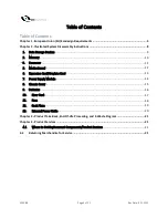
Page 4: ... Memory 10 3 Processor 11 5 Motherboard 12 6 Expansion Card Graphics Card 13 7 Power Supply Module 14 8 Chassis Cover 15 9 Batteries 16 10 Riser Card 17 11 Fans 18 12 Back Plane 19 13 External Power Cable 20 Chapter 3 Product Take Back End Of Life Processing and E Waste Program 21 Chapter 4 Product Services 21 4 1 Where to Get Replacement Components Product Services 21 4 2 Returning Merchandise fo...

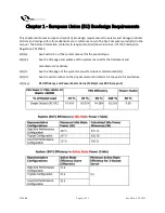
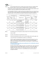
Page 5: ...below information conforms to requirements laid down in Annex II of the Commission Regulation 2019 424 3 1 a See Section 1 1 of the system manual for the product type 3 1 b See the title page and preface of the system manual for the trademark and manufacturer s address 3 1 c See the title page of the system manual for product model number s 3 1 d See the serial number on the physical system to det...

Page 6: ...s is 331 9W 3 1 m The active state efficiency and performance is 26 0 3 1 n There are two methods by which a user can securely delete data from this system The user performing secure data deletion should be an IT professional The first is with a Unified Extensible Firmware Interface UEFI shell utility This utility works on X10 X11 H11 H12 M11 motherboard series with onboard SATA NVMe devices Any u...

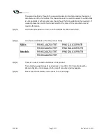
Page 7: ...e of the manufacturer and model information 3 1 o List of recommended combinations of blade servers with chassis N A 3 1 p List of all current SKUs within this product family SKUs PWKS_AA25UTRT PWKS_AA15PWTR Models PWKS1AA25UTRT PWKS1AA15PWTR PWKS2AA25UTRT PWKS2AA15PWTR PWKS4AA25UTRT 3 3 a There is no use of cobalt in batteries in this product The indicative weight range of neodymium in the HDD is...

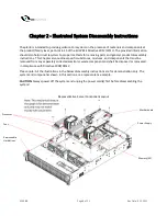
Page 8: ... This Chapter also outlines specific substances mixtures and components that must be removed from any separately collected electronic waste component and shall be disposed or recovered in compliance with Directive 2008 98 EC Please note All the illustrations in the below disassembly instructions are for demonstration only The system and components shown in this section are a representative sample ...

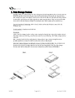
Page 9: ...enings HDD One 1 latch and four 6 Phillips screws SSD 1 Phillips screw Tools required Screwdriver with PH2 bit Procedure HDD Push the release button on the carrier Swing the handle fully Grasp the handle and pull the drive carrier out of its bay once the drive carrier is out of the bay the Phillips screws can be removed SSD Identify the SSD on the motherboard remove the screw and pull straight bac...

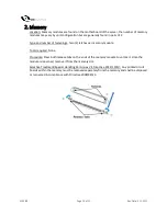
Page 10: ...astenings Two 2 latches per memory module Tools required None Procedure Press both release tabs on the ends of the memory module to unlock it Once the module is loosened remove it from the memory slot Selective Treatment Special Handling Per Annex VII Directive 2012 19 EU Any printed circuit boards within the memory must be removed separately from the memory and shall be disposed or recovered in c...

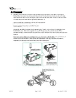
Page 11: ... of fastenings Four 4 T30 Torx screws Tools required Screwdriver with T30 Torx bit Procedure Remove the screws in the sequence of 4 then 3 then 2 then 1 as marked in the illustration below After removing the screws lift the processor heatsink module off the processor socket Unsnap corners A and B then C and D of the latch Push the latch out from the bottom Selective Treatment Special Handling Per ...

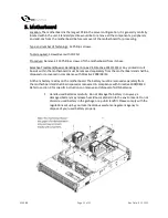
Page 12: ...inted circuit boards within the motherboard must be removed separately from the motherboard and shall be disposed or recovered in compliance with Directive 2008 98 EC A lithium battery resides on the motherboard The battery must be removed separately from the motherboard and shall be disposed or recovered in compliance with Directive 2008 98 EC Refer to section 9 for specific instructions on remov...

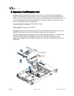
Page 13: ...s integrated should be removed prior to processing the riser card component Type and number of fastenings Six 6 Phillips screws Tools required Screwdriver with PH2 bit Procedure Remove the Phillips screws Open the rear window latch and carefully remove the expansion card from the riser card slot lifting it up and away from the system Selective Treatment Special Handling Per Annex VII Directive 201...

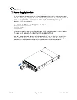
Page 14: ...ies depending on the configuration Type and number of fastenings One 1 latch per module Tools required None Procedure Unplug the power cord from the power supply Push the release tab on the back of the power supply module to the side and pull the module straight out Selective Treatment Special Handling Per Annex VII Directive 2012 19 EU Any printed circuit boards within the power supply module mus...

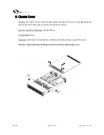
Page 15: ...the server and it approximately 2 3 the size of the entire top as noted in the illustration below Type and number of fastenings Two 2 buttons Tools required None Procedure Hold down the two buttons simultaneously while pushing away the top cover Selective Treatment Special Handling Per Annex VII Directive 2012 19 EU None ...

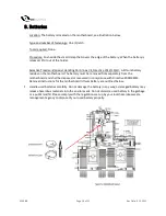
Page 16: ...thium battery resides on the motherboard The battery must be removed from separately from the motherboard and shall be disposed or recovered in compliance with Directive 2008 98 EC Removal instructions for the motherboard lithium battery are outlined below Handle used batteries carefully Do not damage the battery in any way a damaged battery may release hazardous materials into the environment Do ...

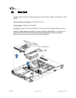
Page 17: ...e 1 Phillips screw Tools required Screwdriver with PH2 bit Procedure Remove the screw and lift the riser card up from the motherboard expansion slot Selective Treatment Special Handling Per Annex VII Directive 2012 19 EU Any printed circuit boards within the riser card must be removed separately from the riser card and shall be disposed or recovered in compliance with Directive 2008 98 EC ...

Page 18: ...r of fastenings One 1 fan header per fan Tools required None Procedure Disconnect the fan wiring from the fan header on the motherboard Then remove the fan from the fan tray Selective Treatment Special Handling Per Annex VII Directive 2012 19 EU Any plastic components within the fan must be removed separately due to the presence of brominated flame retardants and shall be disposed or recovered in ...

Page 19: ... for PWKS_AA25UTRT series and PWKS_AA15PWTR series Tools required Screwdriver with PH2 bit Procedure Disconnect all cables Remove all Phillips screws to release and remove the backplane Selective Treatment Special Handling Per Annex VII Directive 2012 19 EU Any printed circuit boards within the backplane must be removed separately from any other supporting structural components and shall be dispos...

Page 20: ... is fully configured the power supply cord would be connected to the power supply outlet located on the rear of the server chassis Note there are two power supplies per unit so be aware for two power supply cords Type and number of fastenings None direct pressure connection method Tools required None Procedure Disconnect the external power cable from the main server assembly Selective Treatment Sp...

Page 21: ...parts or product service for your system for self replacement or for on site replacement please visit https acecomputers com support and fill out the Ace Computers Support Request form If phone assistance is needed please call our Support Line 847 952 6999 Note Most parts product services are available for at least 5 years after the date of sale Replacement components at a minimum cover the follow...

Reviews: