Chapter
4 Configuration
Installation and Operation Manual
4-120 Configuring for Operation
ACE-3105, ACE-3205 Ver. 5.2
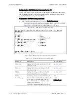
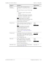
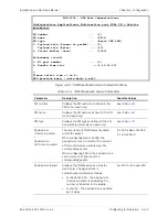
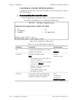
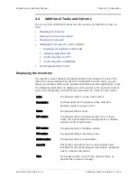
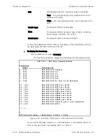
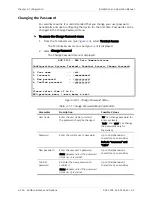
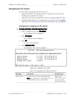
Parameter Description
Possible
Values
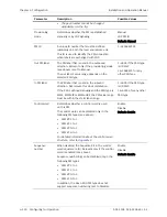
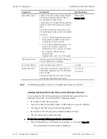
Jitter buffer (
μ
sec)
Length of the jitter buffer's delay towards
the transmit direction (PSN to TDM), in
microseconds. The jitter buffer
compensates for the packet delay variation
tolerance (PDVT) and for general network
jitter.
The minimum value cannot be lower than
the packetization delay, which is calculated
as follows:
•
For E1/T1 CES PSN packetization delay –
the payload size (frames in packet) is
doubled by 125 microseconds.
•
For T1 SAToP packetization delay – the
payload size (frames in packet) is
doubled by 32, then the sum is divided
by 24 and then doubled by 125
microseconds:
{[payload size
32] : 24}
125
μ
secs.
1000–32000
Default: 3000
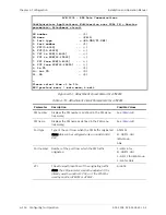
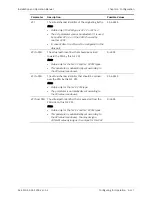
Attachment circuit
Heading under which the TDM attachment
circuit parameters are displayed
E1/T1 port number
Circuit emulation port number
1–4/8/16
Bundle time slots
The number of timeslots in the Basic CES
PSN bundle. Available only if the PW type is
Basic CES PSN.
The same bundle time slot cannot be used
in more than one attachment circuit.
1–31 for E1
1–24 for T1
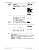
All TDM PW parameters cannot be changed dynamically (on-the-fly).
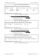
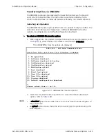
Viewing Existing PW Connections and Attachment Circuits
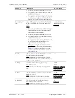
You can view the list of all pseudowire connections that were defined for
ACE-3105, ACE-3205. The list provide the following details:
•
ID number of each PW connection
•
Type of the PW (encapsulation type) or PW subtype in case of CESoPSN
•
The type of the PSN on which the PW established
•
ID number of the remote peer on which the PW terminates
•
The Out Label and In Label of the PW.
³
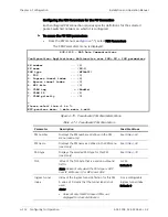
To view the currently defined pseudowire connections:
•
From the Multiservice over PSN menu (see
), select View PW.
The pseudowire connections list is displayed.
Note

