Installation and Operation Manual
Chapter
6 Monitoring and Diagnostics
ACE-3105, ACE-3205 Ver. 5.2
Recovering ACE Units
6-83
6.6
Recovering ACE Units
This section highlights possible scenarios that may have led to failure. It explains
how to recover ACE-3105, ACE-3205 assuming those scenarios.
This section applies to Version 5.2 of all devices that belong to the ACE-3000
family. Certain scenarios and possible solutions may therefore not apply to your
specific ACE unit.
ACR Failure
The ACE device features an Adaptive Clock Recovery (ACR) mechanism, designed
to track a synchronous clock source over PSN-based networks. The mechanism
utilizes a dedicated Uni-Directional PW for the clock recovery process running
between the Distribution unit and the Recovery unit.
The issues in need to be addressed:
•
Status of the clock recovery PW
•
Status of the remote port generating the clock stream.
Determining the Condition of the Clock Recovery PW
³
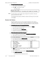
To determine the condition of the Clock Recovery PW:
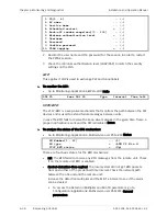
1.
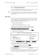
Go to Monitoring>Applications>Multiservice over PSN>PW>Status.
2.
Select the clock recovery PW index.
ACE-3400 – RAD Data Communications
Monitoring> Applications> Multi service over PSN> PW> Status
PW type > (Clock Recovery)
Operational status > (Up)
Local status ... (Forwarding)
Local status faults ... (No faults)
3.
Ensure that Operational Status is Up and Local Status set to Forwarding.
If the ACR PW is in Down state, continue investigating using the PW/VCCV-BFD
Failure procedure (RAT Entry #3), as outlined below:
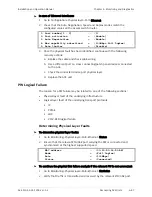
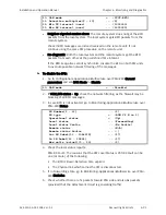
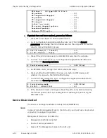
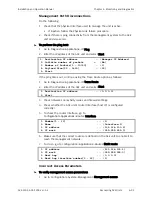
1.
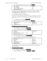
Go to Monitoring>System>Clock>Recovered clock>Status.
2.
Select Recovered ID and observe the status of the ACR.
Clock State > (Holdover)
1. Recovered ID[1 - 1] ... (1)
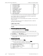
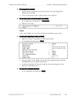
In case of an ACR failure, the clock should be in Holdover state, which keeps the
last known clock frequency and maintains it with a +/- 1ppb offset per day.
Note

