Installation and Operation Manual
Chapter
6 Monitoring and Diagnostics
ACE-3105, ACE-3205 Ver. 5.2
Recovering ACE Units
6-87
³
In case of Ethernet interfaces:
1.
Go to Configuration>Physical layer>Port>Ethernet.
2.
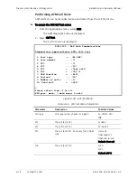
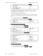
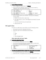
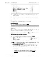
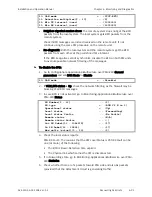
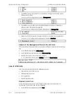
Check that the Auto Negotiation, Speed and Duplex modes match the
configured values on the access switch/router.
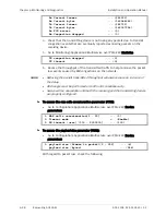
1. Port number[1 - 2] ... (1)
2. Port activation > (Enable)
3. Auto Negotiation > (Enable)
4. Max capability advertised > (100Mbps Full Duplex)
5. Rate limiter > (Disable)
3.
Once the physical fault has been identified, continue with the following
recovery actions:
a.
Replace the cable and check cable wiring.
b.
Use a different port on cross connecting/patch panel devices connected
to the ACE.
c.
Check the connected device port physical layer.
d.
Replace the ACE unit.
PW Logical Failure
The reason for a PW failure may be related to one of the following sections:
•
Physical layer fault of the underlying infrastructure
•
Logical layer fault of the underlying transport protocols:
IP
PPPoE
LDP
VCCV-BFD logical failure.
Determining Physical Layer Faults
³
To determine physical layer faults:
1.
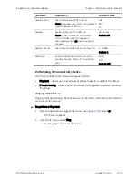
Go to Monitoring>Physical layer>Port>Ethernet>Status.
2.
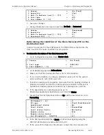
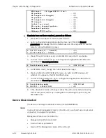
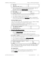
Ensure that the relevant ETH/GbE port carrying the PW is connected and
synchronized at the highest supported speed.
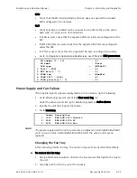
MAC address ... (00-20-D2-28-D1-AB)
Mode > (Full Duplex)
Rate > (100Mbps)
Status > (Connected)
³
To continue the physical link failure analysis if the relevant PW is not connected:
1.
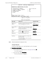
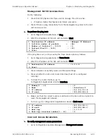
Go to Monitoring>Physical layer>Port>Ethernet>Statistics.
2.
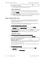
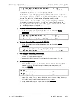
Verify that traffic is transmitted and received by the relevant ETH/GbE port.

