Chapter
6 Monitoring and Diagnostics
Installation and Operation Manual
6-106
Recovering ACE Units
ACE-3105, ACE-3205 Ver. 5.2
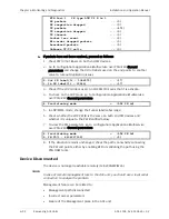
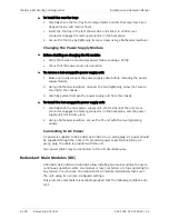
If the underrun is also associated with the Rx L|M=100 alarm, check the status of
the remote DATA interface (not the clocking interface). To do so, do the
following:
1.
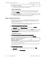
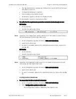
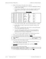
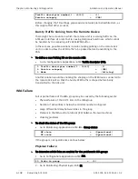
Go to Monitoring>Physical layer>Port>E1.
LOS ... (0
FEBE
... (0)
LOF
... (0) BES
... (0)
LCV ... (0)
DM
... (0)
LCD
... (0) ES
... (0)
RAI ... (0)
SES
... (0)
AIS ... (0) UAS
... (0)
Rx frame slips ... (0)
If LOS or AIS are increasing, the attached PW will not be sending traffic to the
remote unit.
2.
In case of LOS, continue using the Physical Link failure procedure.
3.
In case of AIS, check the connected equipment for the reason it is generating
AIS towards the ACE unit.
Rx Congestions
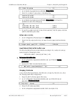
This may occur if the buffer located between the PW packets towards the ATM
has overflowed.
The Rx Congestion dropped counter represents the number of packets dropped
due to congestion on the receive direction, i.e. from the PSN side to the ATM
direction.(Packet Delay Variation) Buffer is used to compensate for PDV in PSN
networks.
³
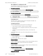
To check the Rx Congestion counter for amount and frequency of dropped
packets:
•
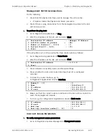
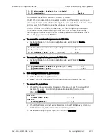
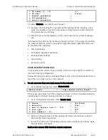
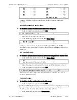
Go to Monitoring>Applications>Multiservice over PSN>PW>Statistics.
RX congestion dropped
... (0)
Possible causes:
•
ATM BW issues
•
Insufficient PSN
Æ
ATM buffer size
•
Shaping problems
•
Bursty traffic coming from the remote device.
ATM Bandwidth issues
Check that the ATM attachment circuit related to the PW is providing the
expected amount of bandwidth:
IMA
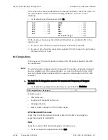
Check the number of E1 links belonging to the IMA group:
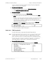
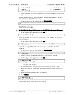
1.
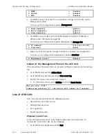
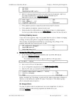
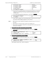
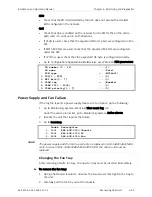
Go to Configuration>Applications>ATM>IMA.
Note

