Installation and Operation Manual
Chapter
6 Monitoring and Diagnostics
ACE-3105, ACE-3205 Ver. 5.2
Recovering ACE Units
6-109
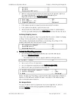
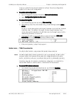
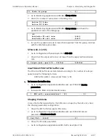
LOS ... (0) FEBE ... (0)
LOF ... (0) BES ... (0)
LCV ... (0) DM ... (0)
LCD ... (0) ES ... (0)
RAI ... (0) SES ... (0)
AIS ... (0) UAS ... (0)
Rx frame slips ... (0)
In case of LOS alarm, continue investigation using the Physical Link failure
procedure.
Minimal number of active links
³
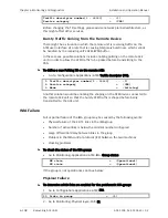
To check the number of minimal active links in the IMA group:
1.
Go to Configuration>Applications>ATM>IMA.
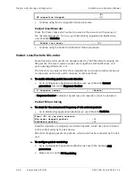
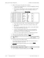
3. Min RX/TX links[1 - 16]
... (1)
2.
Check the actual number of active links.
3.
Go to Monitoring>Applications>ATM>IMA>Group status.
Active TX links
... (1)
Active RX links
... (1)
In case of a lower number, try to reduce the Min Rx/Tx links under the IMA
configuration to a lower value in order to allow the operating links to restore the
IMA group.
Differential delay
³
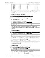
To check the current observed maximum differential delay between the IMA links:
1.
Go to Monitoring>Applications>ATM>IMA>Group status.
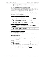
... (N)
Max observed differential delay ... (0)
2.
Check the value does not exceeds the maximum differential delay allowed.
3.
Go to Configuration>Applications>ATM>IMA.
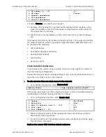
6. Max differential delay (ms)[1 - 100] ... (25)
If the observed value is higher than the permitted one, increase the allowed
maximum differential delay.
Clocking issues
³
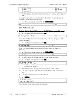
To check the clocking configuration on the IMA group:
•
Go to Configuration>Applications>ATM>IMA.
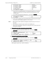
9. Common TX clock source > (System)
If set to system, check the status of the current clock as follows:
1.
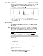
Go to Monitoring>System>Clock>Current clock.

