Installation and Operation Manual
Appendix
C ATM OAM Functionality
ACE-3105, ACE-3205 Ver. 5.2
OAM Modes of Operation over ATM
C-3
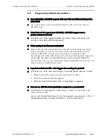
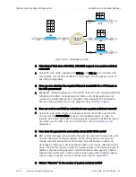
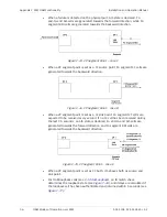
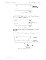
When a failure is detected on the physical port, AIS state is declared and
F4 end-to-end AIS cells are generated towards the forward direction.
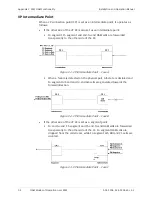
Figure
C-4. VP Intermediate Point – Case D
•
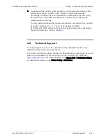
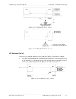
For OAM loopback cells (see
), an ID match check
determines the loopback state:
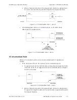
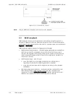
Figure
C-5. VP Intermediate Point – Case E
VC Intermediate Point
When a VC connection point is set as an intermediate point, it operates as
follows:
•
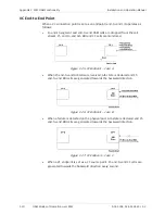
If the other side of the VC XC is also set as an intermediate point:
F5 segment and end-to-end OAM cells are forwarded transparently to the
other side of the XC. F4 segment and end-to-end OAM cells are dropped
from the cell stream.
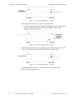
Figure
C-6. VC Intermediate Point – Case A
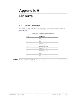
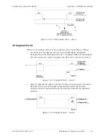
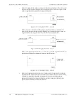
When a failure is detected on the physical port, AIS state is declared and
F5 segment AIS together with end-to-end AIS cells are generated towards
the forward direction.

