Chapter
1 Introduction
Installation and Operation Manual
1-10 Functional
Description
ACE-3105, ACE-3205 Ver. 5.2
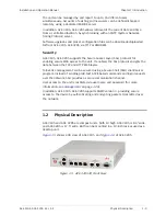
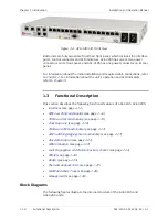
Figure
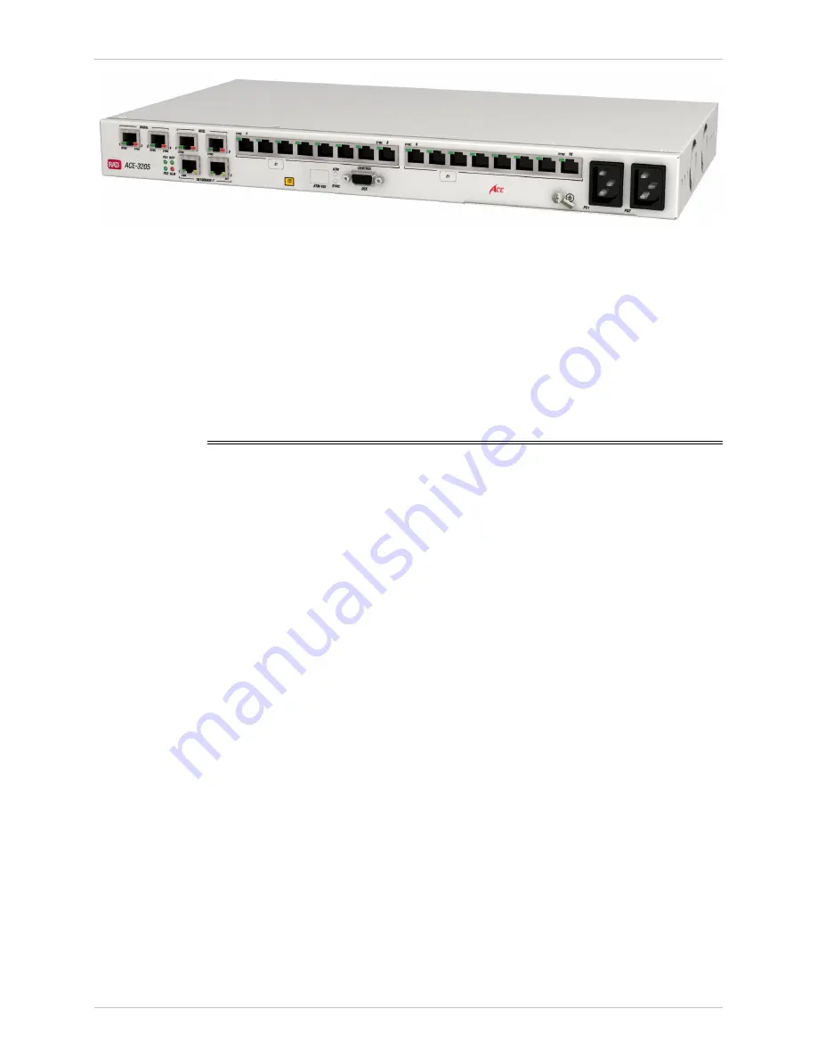
1-6. ACE-3205 3D Front View
Both units are fully accessible from their front panel, which includes the interface
ports, control connector and LED indicators. ACE-3205 has one or two power
connectors on its front panel, and ACE-3105 has one power connector on its rear
panel.
For information about the initial installation and required cable connections, refer
to
. For information about the unit's operation and LED indicators,
1.3
Functional Description
This section describes the following functional features of ACE-3105, ACE-3205:
•
(see page
)
•
(see page
)
•
(see page
)
•
(see page
)
•
(see page
)
•
ATM Switching/Aggregation Functionality
(see page
)
•
(see page
)
•
(see page
)
•
Fault Propagation and PSN Connectivity Checks
(see page
)
•
(see page
)
•
(see page
)
•
(see page
)
•
(see page
)
•
(see page
).
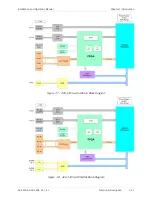
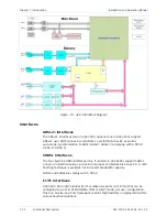
Block Diagrams
The following figures illustrate the internal structure of the ACE-3105 and
ACE-3205 units:

