Installation and Operation Manual
Appendix
E Encapsulation over PSN
ACE-3105, ACE-3205 Ver. 5.2
3BATM Service Encapsulation
E-9
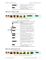
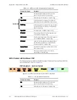
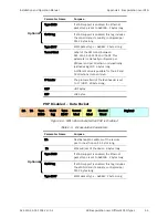
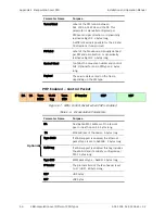
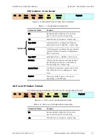
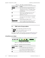
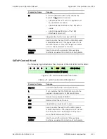
Parameter Name
Purpose
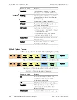
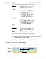
PPP header
Identifies the PPP payload and set to 0x21
to indicate an IP frame. 2 bytes long.
IP header
20 bytes long and contains:
•
Source IP of the device, as was learned
by the PPP/IPCP session
•
Destination IP of the remote peer
(configured manually)
•
Protocol field of the IP header; can be
either UDP (17) or MPLS in IP (137),
depending on the PW configuration.
UDP header
Used only for UDP traffic.
8 bytes long and contains:
•
UDP source port – identifies the PW label
of the destination unit
•
UDP destination Port – uses TDMoIP
protocol number: 0x85E (2142)
PW Label
Used only for MPLS in IP mode.
Manually defined per PW and per direction.
4 bytes long.
Control Word
Contains the sequence number and control
bits. Optional for some PW types. 4 bytes
long.
Payload
The service data carried on the frame,
depending on the PW type.
E.3
ATM Service Encapsulation
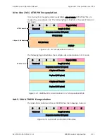
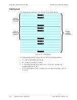
ATM traffic is encapsulated in either the one-to-one or N-to-1 mode.
One-to-One (1:1) ATM PW Encapsulation
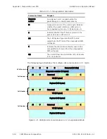
In the one-to-one (1:1) ATM PW mapping mode (selectable), one ATM VCC/VPC is
mapped to a single pseudowire link. The following figure illustrates the packet
format in 1:1 mode:
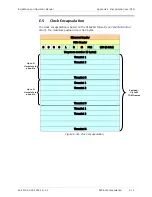
0
0
0
0
Reserved (4 bits)
Sequence number (2 bytes)
M
V
Reserved
PTI
C
VCI (2 bytes)
Figure
E-12. 1:1 Encapsulation Structure
ATM Control
Cell Header

