Chapter
1 Introduction
Installation and Operation Manual
1-20 Functional
Description
ACE-3105, ACE-3205 Ver. 5.2
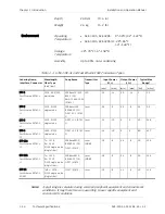
Port Type
Minimum CDVT
TDM
1 cell time at line rate
UPI multi-PHY
4 cell time at line rate
UPI single-PHY
16 cell time at line rate
IMA
1 cell time at minimum IMA
group rate
Equal-rate-slow-PHY (ERSP)
1 cell time at line rate
ATM Buffer Allocations
ACE-3105, ACE-3205 has three types of fixed congestion thresholds:
•
Global – the maximum number of cells that can be allocated/buffered for all
service categories is 64,000.
•
Service category – the maximum number of cells that can be
allocated/buffered for each traffic class is 16,000.
•
Per connection – the maximum number of cells that can be allocated/buffered
for each connection is 1024.
IMA Functionality
ACE-3105, ACE-3205 supports IMA (Inverse Multiplexing over ATM) versions 1.0
and 1.1. It can bundle together up to 4 or 8/16 IMA groups, and up to 4/8/16
independent links (depending on number of E1/T1 ports) per IMA group.
In addition, ACE-3105, ACE-3205 supports Common Transmit Clock (CTC), along
with a differential delay of up to 100 ms for the E1/T1 interface.
The CTC may be derived from the system clock or from the internal clock.
The unit's clock can be derived from the TRL of an IMA group. For more
information, refer to
All possible IMA frame sizes are supported: 32, 64, 128 and 256.
ATM OAM Functionality
ACE-3105, ACE-3205 provides F4/F5 OAM support that complies with ITU-I.610
(AIS, RDI and CC). OAM cells are inserted into the VP/VC cell stream ahead of the
shaper, enabling accurate conformance to shaping parameters.
Four operating modes are supported:
•
End-to-end (for a host only)
•
Segment
•
Intermediate
•
Loopback – OAM loopback cells are used to determine connectivity at specific
points in a network or between networks. OAM cells are part of the F4 and
F5 OAM service, which allows fault management for VPs and VCs. Loopback
cells can be defined as Segment or End-to-End.
Note

