Chapter
2 Installation and Setup
Installation and Operation Manual
2-6
Connecting to Packet-Switched Networks
ACE-3105, ACE-3205 Ver. 5.2
Figure
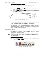
2-8. Locking the SFP Wire Latch
2.
Carefully remove the dust covers from the SFP module.
3.
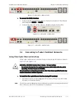
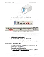
Install the required SFP module by inserting it into the appropriate module
slot until it clicks into place.
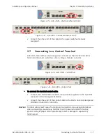
Figure
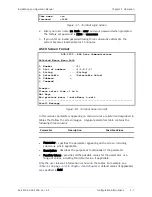
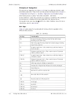
2-9. ACE-3105 – Optical Ethernet Ports (empty slots)
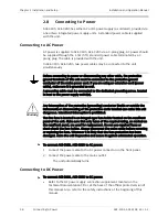
Figure
2-10. ACE-3205 – Optical Ethernet Ports (empty slots)
If the SFP module does not click into place, remove the SFP, lock it properly and
then re-insert the SFP module into the ATM port.
³
To disconnect the fiber optic interface:
1.
Disconnect the fiber optic cables from the SFP module.
2.
Unlock the wire latch by lowering it downwards (as opposed to locking).
3.
Hold the wire latch and gently pull the SFP module out of the Ethernet port.
Using Electrical Ethernet Interface
The electrical Ethernet interface terminates in an 8-pin RJ-45 connector (for
connector pinouts, see
³
To connect the electrical Ethernet interface:
1.
Connect a Cat. 5 cable to the RJ-45 connector of the Ethernet port labeled
10/100/1000BASE-T 1 or 10/100/1000BASE-T 2.
Note


