Chapter
3 Operation
Installation and Operation Manual
3-2 LED
Indicators
ACE-3105, ACE-3205 Ver. 5.2
3.2
LED Indicators
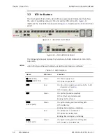
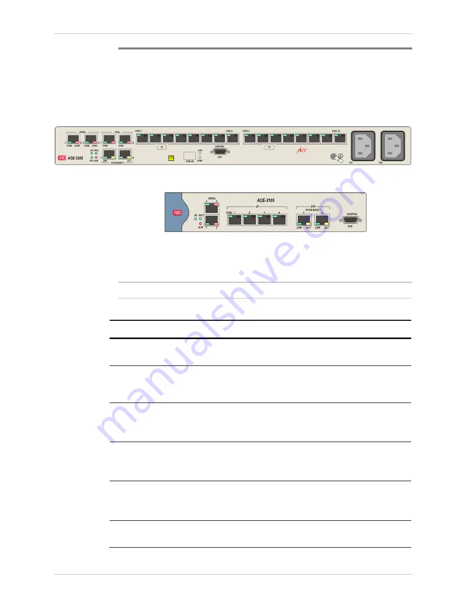
The front panel of ACE-3105, ACE-3205 incorporates LED indicators that show
the current operating status of the unit and its different ports.
illustrates the ACE-3205 front panel and
illustrates the ACE-3105 front
panel:
Figure
3-1. ACE-3205 Front Panel
Figure
3-2. ACE-3105 Front Panel
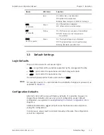
The following table summarizes the function of all LED indicators in ACE-3105,
ACE-3205.
ACE-3105 ships either with ADSL2+ or SHDSL interfaces (as ordered)
Table
3-1. LED Indicators
Name LED
Color
Function
PS (ACE-3105)
PS1/PS2 (ACE-3205)
Green
On: Power supply is on
Off: Power supply is off
ALM
Red
On: One or more alarms are active. Refer to list
of alarms in
Chapter 6
Off: No active alarms
RDY
Green
On: Self-test ended successfully
Off: Self-test not started/ended
Blinking: Self-test failed
SYNC
(ADSL2 ports)
Green
On: Synchronizing and transmitting data
Off: No DSL link
Blinking: Red and green, initializing
Red
On: ADSL2 link is not detected
Off: ADSL2 link is detected
Blinking: Read and green, initializing
SYNC
(SHDSL ports)
Green
On: Synchronizing and transmitting data
Off: No data or no SHDSL link
Note

