Chapter
4 Configuration
Installation and Operation Manual
4-60
Configuring for Operation
ACE-3105, ACE-3205 Ver. 5.2
ACE-3200 – RAD Data Communications
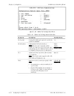
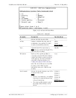
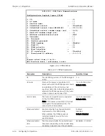
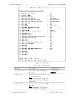
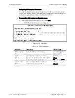
Configuration> Logical layer> Abis
1. Logical port number ... (1)
2. E1 port number ... (1)
3. Timeslot numbers ... (1-31)
4. Uplink TX direction > (Upstream)
5. Upstream optimization mode > (Optimization)
6. Downstream optimization mode > (Optimization)
7. Byte reversal > (Yes)
8. TX jitter > (20)
9. Idle TRAU > (Idle PCM)
10. Silence suppression rate > (98)
11. Silence TRAU > (Last received)
12. GPRS frame > (TRAU)
13. Unknown frame optimization > (Disable)
14. Signaling VPI ... (1)
15. Signaling VCI ... (1)
16. Signaling multiplexed frame size ... (500)
17. Signaling TX interval ... (20)
18. Voice VPI ... (1)
19. Voice VCI ... (1)
20. Voice multiplexed frame size ... (500)
21. Voice TX interval ... (20)
22. Data VPI ... (1)
23. Data VCI ... (1)
24. Data multiplexed frame size ... (500)
25. Data TX interval ... (20)
26. Timeslot >
27. Statistics >
28. Advanced >
>
Please select item <1 to 28>
ESC-Previous menu; !-main menu; &-exit
Figure
4-46. Abis Menu
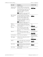
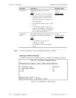
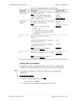
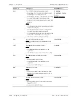
Table
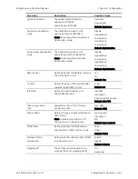
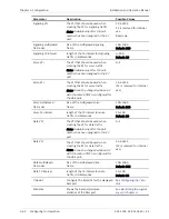
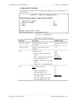
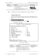
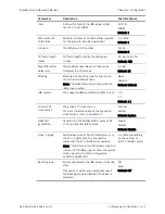
4-39. Abis Parameters
Parameter Description
Possible
Values
Logical port number
A unique ID number for the logical
Abis port
1–4294967295
Default: 1
E1 port number
The physical E1 port number to be used
as the logical Abis port
Note: The relevant E1 port must be set
to Abis in advance (from the Physical
Layer menu)
1–6
Timeslot numbers
Time slot numbers associated with the
Abis port
Note: Available after the logical port
has been selected and configured
1–31

