Chapter
6 Monitoring and Diagnostics
Installation and Operation Manual
6-38
Monitoring Performance
ACE-3105, ACE-3205 Ver. 5.2
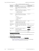
Table
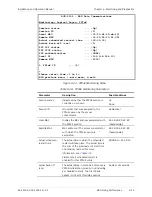
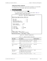
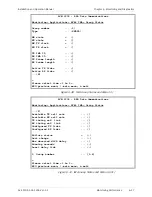
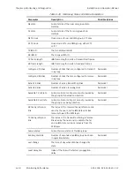
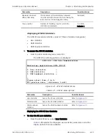
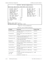
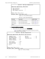
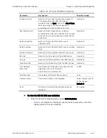
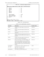
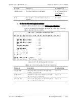
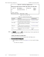
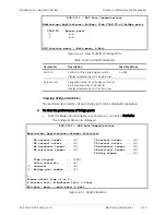
6-26. IMA Group Status and Menu Parameters
Parameter Description
Possible
Values
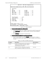
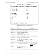
NE state
Current state of the near end group state
machine
FE state
Current state of the far end group state
machine
NE TX clock
Clock mode of near end IMA group, CTC only
FE TX clock
Clock mode of far end IMA group, either CTC
or ITC
TX IMA ID
The transmitted IMA ID
RX IMA ID
The received IMA ID
TX frame length
IMA frame length in cells of transmitted frames
RX frame length
IMA frame length in cells of received frames
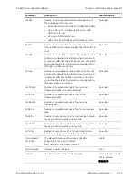
Configured TX links
Number of links that are configured to transmit
in a group
Numerical
Configured RX links
Number of links that are configured to receive
in a group
Numerical
Active TX links
Number of active transmitting links
Numerical
Active RX links
Number of active receiving links
Numerical
Available TX cell rate
Current cell rate (cells per second) provided by
the group in transmission direction.
Numerical
Available RX cell rate
Current cell rate (cells per second) provided by
the group in receiving direction.
Numerical
RX timing reference
link
The index of the received timing reference link
used by the near end for IMA data cell clock
recovery toward the ATM layer.
TX timing reference
link
The index of the transmitted timing reference
link used by the near end to indicate the far
end on IMA data cell clock recovery from the
ATM layer.
Failure status
Current failure status of the IMA group
Running seconds
Number of seconds since IMA group has been
in operational state.
Numerical
Last change
The time of day when IMA has changed its
state
Least delay link
Index of the link with shortest propagation
delay

