Installation and Operation Manual
Chapter
6 Monitoring and Diagnostics
ACE-3105, ACE-3205 Ver. 5.2
Troubleshooting
6-81
ACE-3205 – RAD Data Communications
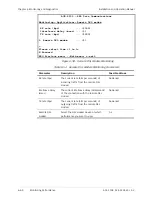
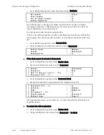
Diagnostics> Applications> IP> Trace Route
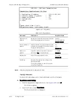
1. Destination IP address ... (100.10.151.201)
2. Start
>
Please select item <1 to 2>
ESC-previous menu; !-main menu; &-exit
Figure
6-68. Trace Route Menu
Table
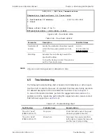
6-66. Trace Route Options
Parameter Description
Possible
Values
Destination IP
address
Specify the destination IP address towards
which the trace-route packets are to be
sent
0.0.0.0–
255.255.255.255
Default: 0.0.0.0
Start/Stop
Activates the route tracing towards the
specified IP address.
To stop the tracing, re-select this option or
exit the Trace Route menu.
Only one route tracing session is allowed at a time.
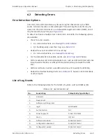
6.5
Troubleshooting
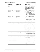
The following troubleshooting chart is based on LED indications or other inputs.
Use this chart to identify the cause of a problem that may arise during operation.
For detailed description of the LED indicators functions, refer to
To correct the reported problem, perform the suggested remedy actions. If a
problem cannot be resolved by performing the suggested action, please contact
RAD technical support (see
).
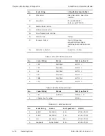
Table
6-67. Troubleshooting Chart
Fault/Problem
Probable Cause
Remedy Action
The unit is “dead”
(POWER LED is off)
No power
Check that both ends of the power
cable are properly connected.
The unit is “dead”
(POWER LED is off)
Blown fuse
Disconnect the power cable from
both ends and replace the fuse with
another fuse of proper rating.
Note

