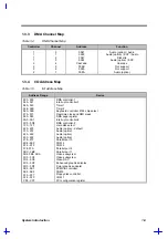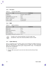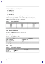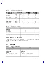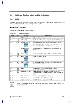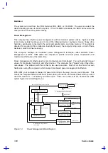
System Introduction
1-3
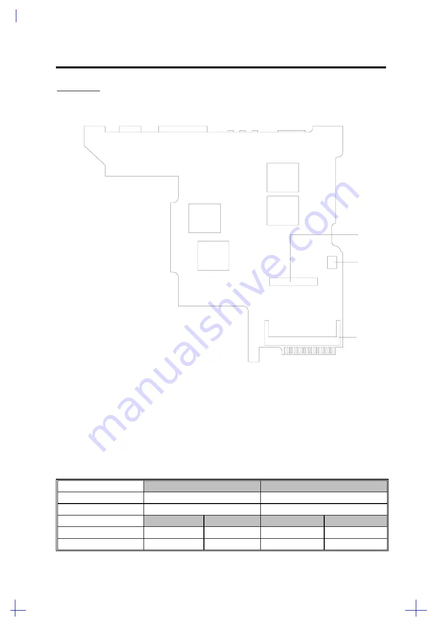
BOTTOM VIEW
CN19
Modem connector
CN20
Modem connector
CN21
DIMM socket
Figure 1-2
Jumpers and Connectors (Bottom View)
The following tables list the switch settings for SW1.
Table 1-1
SW1 Switch Settings
ON
OFF
Switch 1 (Logo Screen)
OEM
Acer
Switch 2 (Password)
Bypass
Check
English
European
Japanese
Korean
Switch 3 (KB Language)
Off
On
Off
On
Switch 4 (KB Language)
Off
Off
On
On
CN20
CN19
CN21
PCB No. 97160-1
Summary of Contents for 365 Series
Page 80: ...Silk Screen D 2 PCB No 96532 SA CPU Board Layout Bottom ...
Page 82: ...Mainboard Layout ...
Page 83: ...Bottom ...
Page 95: ... S S S H Q G S H Q G L L Explored View Diagram ...
Page 96: ......
Page 100: ......
Page 101: ......
Page 115: ......
Page 117: ......
Page 120: ......
Page 122: ......
Page 126: ......


