vii
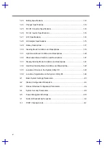
Disassembling the Inside Frame Assembly ................................................. 3-12
Removing the Heat Sink Assembly............................................... 3-12
Removing the Display ................................................................... 3-13
Removing the Internal Drive ......................................................... 3-14
Replacing the CPU ....................................................................... 3-15
Detaching the Top Cover .............................................................. 3-16
Removing the Mainboard.............................................................. 3-17
Disassembling the Mainboard....................................................... 3-19
Disassembling the Top Cover....................................................... 3-20
Appendices
Appendix A Model Number Definition
Appendix B Compatibility Test Report Excerpt
Appendix C BIOS POST Checkpoint
Appendix F Explored View Diagram
Appendix H Ttroubleshooting to Board Repairing
List of Figures
Jumpers and Connectors (Top View)............................................................. 1-2
Jumpers and Connectors (Bottom View) ....................................................... 1-3
Power Management Block Diagram............................................................. 1-18
Using Connectors With Locks ........................................................................ 3-3
Summary of Contents for 365 Series
Page 80: ...Silk Screen D 2 PCB No 96532 SA CPU Board Layout Bottom ...
Page 82: ...Mainboard Layout ...
Page 83: ...Bottom ...
Page 95: ... S S S H Q G S H Q G L L Explored View Diagram ...
Page 96: ......
Page 100: ......
Page 101: ......
Page 115: ......
Page 117: ......
Page 120: ......
Page 122: ......
Page 126: ......

