Disassembly and Unit Replacement
3-23
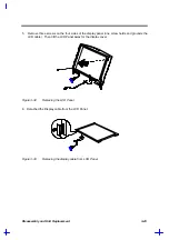
5.
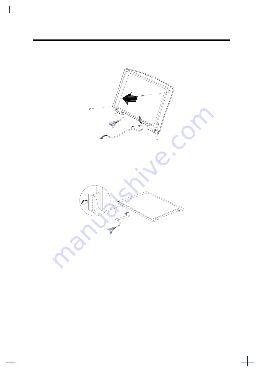
Remove three screws on the four sides of the display panel (one screw holds and grounds the
LCD cable). Then tilt the LCD Panel away for the display cover.
Figure 3-32
Removing the LCD Panel
6. Detached the Display cable from the LCD Panel.
Figure 3-33
Removing the display cable from LCD Panel
Summary of Contents for 365 Series
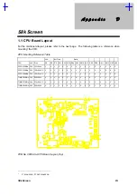
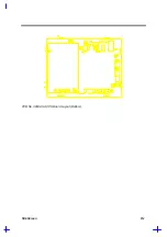
Page 80: ...Silk Screen D 2 PCB No 96532 SA CPU Board Layout Bottom ...
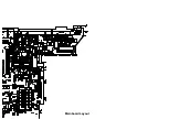
Page 82: ...Mainboard Layout ...
Page 83: ...Bottom ...
Page 95: ... S S S H Q G S H Q G L L Explored View Diagram ...
Page 96: ......
Page 100: ......
Page 101: ......
Page 115: ......
Page 117: ......
Page 120: ......
Page 122: ......
Page 126: ......

