viii
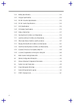
Disassembly Sequence Flowchart ................................................................. 3-5
Removing the Memory Door........................................................................... 3-6
Installing and Removing Memory ................................................................... 3-7
Removing the Modem Board.......................................................................... 3-8
Removing the Hard Disk Drive ....................................................................... 3-9
Removing the Display Hinge Covers............................................................ 3-10
Unplugging the Keyboard Connectors.......................................................... 3-11
Removing the LED Cover............................................................................. 3-12
Removing the Heat Sink Assembly .............................................................. 3-12
Unplugging the Display Cable ...................................................................... 3-13
Removing the Display Hinge Screws ........................................................... 3-13
Removing the Display Hinge Screws ........................................................... 3-14
Cables ......................................................................................... 3-16
Cables ......................................................................................... 3-16
Removing the DC-DC Converter Board ....................................................... 3-18
Removing the Mainboard ............................................................................. 3-18
Removing the Charger Board....................................................................... 3-19
Removing the PCMCIA Sockets .................................................................. 3-19
Removing the Hard Disk Drive Heat Sink .................................................... 3-20
Removing the Touchpad and Speakers ....................................................... 3-20
Removing the LCD Bumpers........................................................................ 3-21
Removing the Display Bezel Screws ............................................................ 3-21
Summary of Contents for 365 Series
Page 80: ...Silk Screen D 2 PCB No 96532 SA CPU Board Layout Bottom ...
Page 82: ...Mainboard Layout ...
Page 83: ...Bottom ...
Page 95: ... S S S H Q G S H Q G L L Explored View Diagram ...
Page 96: ......
Page 100: ......
Page 101: ......
Page 115: ......
Page 117: ......
Page 120: ......
Page 122: ......
Page 126: ......

