Chapter 3
57
Removing the Switch Cover
CAUTION:
Using metal tools to remove the Switch Cover may cause damage to the outer casing. It is
recommended that only fingers or a plastic pry are used to remove the Switch Cover.
1.
See “Removing the Battery Pack” on page 44.
2.
See “Removing the Hinge Covers” on page 56.
3.
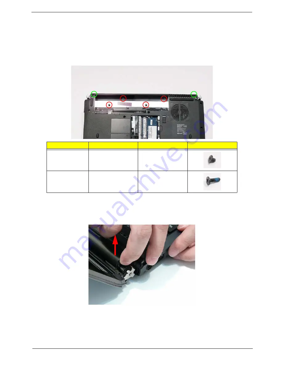
Locate and remove the six securing screws on the bottom of the computer.
4.
Turn the computer over and open the LCD module to expose the Switch Cover.
IMPORTANT:
The LCD module does not fully extend. Damage will occur if you attempt to extend the LCD module
beyond the manufacturer’s design.
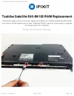
5.
Lift the left side of Switch Cover, hinge cover first as shown.
Step
Size
Quantity
Screw Type
Switch Cover
(red callout)
M2.5*3
4
Switch Cover
(green callout)
M2.5*10
2
Summary of Contents for 4535 5133 - Aspire - Athlon X2 2.1 GHz
Page 6: ...VI ...
Page 44: ...Chapter 2 35 A progress screen displays ...
Page 49: ...40 Chapter 2 2 In DOS mode run the MAC BAT file to write MAC values to eeprom ...
Page 56: ...Chapter 3 47 5 Remove the HDD Cover as shown ...
Page 98: ...Chapter 3 89 4 Lift the bezel away from the panel ...
Page 101: ...92 Chapter 3 4 Lift the LCD Panel out of the casing as shown ...
Page 125: ...116 Chapter 3 4 Replace the single securing screw ...
Page 147: ...138 Chapter 3 ...
Page 194: ...Chapter 6 185 ...
Page 219: ...Appendix A 210 ...
Page 249: ...240 Appendix B ...
Page 251: ...242 Appendix C ...


