162
Chapter 5
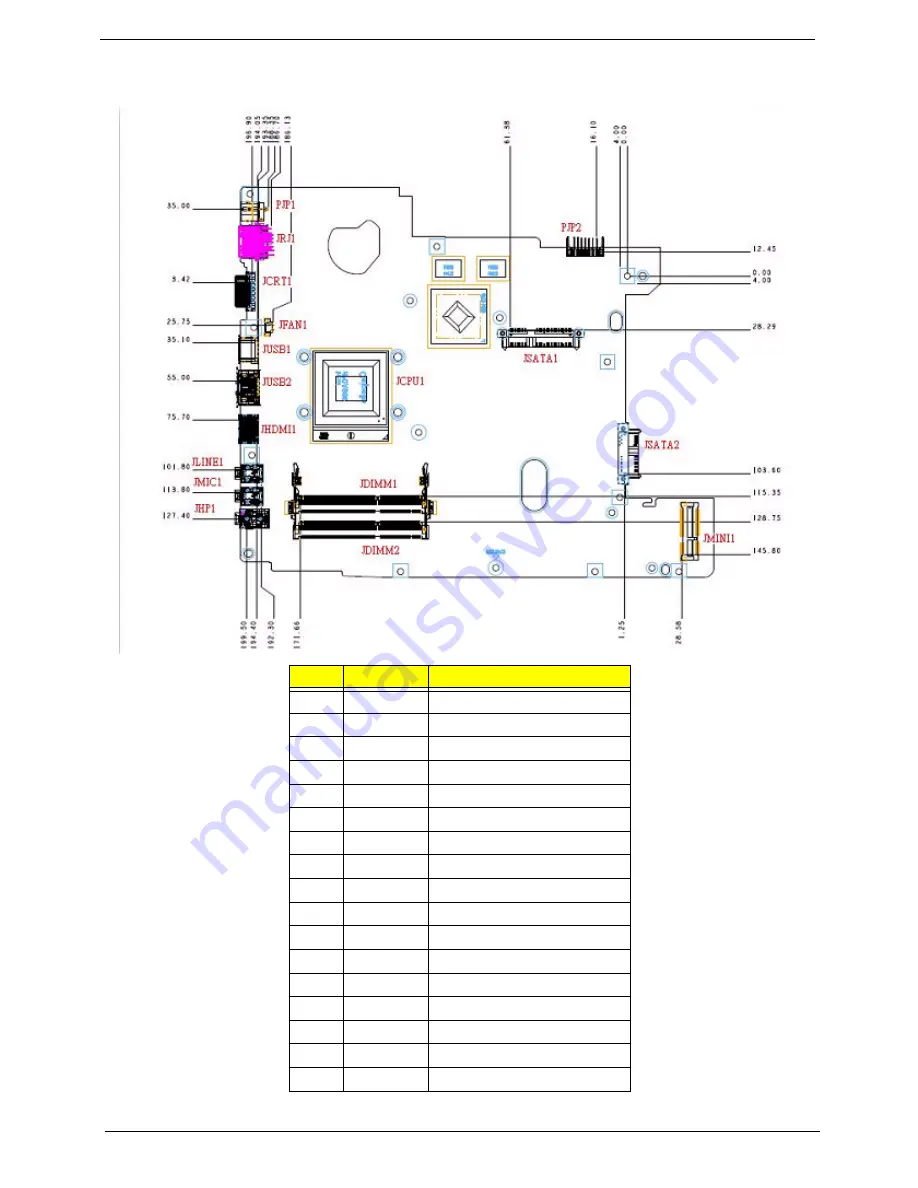
Bottom View
Item
Pin
Description
1
PJP1
DC IN Connector
2
JRJ1
Lan Connector
3
JCRT1
CRT Connector
4
JFAN1
Fan Connector
5
JUSB1
USB Connector
6
JUSB2
USB Connector
7
JHDMI1
HDMI Connector
8
JLINE1
Line In Connector
9
JMIC1
External Mic Connector
10
JHP1
Head Phone Connector
11
JCPU1
Cpu Socket Connector
12
JDIMM1
DRAM Socket Connector
13
JDIMM2
DRAM Socket Connector
14
PJP2
Battery Charger Connector
15
JSATA1
HDD Connector
16
JSATA2
ODD Connector
17
JMINI1
Mini Card Connector
Summary of Contents for 4740G series
Page 6: ...VI ...
Page 10: ...X Table of Contents ...
Page 56: ...46 Chapter 2 ...
Page 63: ...Chapter 3 53 5 Carefully open the HDD Cover ...
Page 65: ...Chapter 3 55 5 Remove two 2 screws from the WLAN bracket and lift it clear of the device ...
Page 90: ...80 Chapter 3 5 Remove the TouchPad Bracket from the Upper Cover ...
Page 92: ...82 Chapter 3 Step Size Quantity Screw Type Media Board M2 5 3 2 ...
Page 97: ...Chapter 3 87 Step Size Quantity Screw Type Bluetooth Module M2 5 3 1 ...
Page 99: ...Chapter 3 89 7 Lift one edge of the mainboard as shown to remove it from the base ...
Page 107: ...Chapter 3 97 4 Lift the bezel away from the panel ...
Page 110: ...100 Chapter 3 4 Lift the LCD Panel out of the casing as shown ...
Page 117: ...Chapter 3 107 13 Ensure that the securing pin is properly located ...
Page 129: ...Chapter 3 119 ...
Page 134: ...124 Chapter 3 4 Turn the computer over Replace the fifteen screws on the bottom panel ...
Page 141: ...Chapter 3 131 4 Turn the computer over and replace the six 6 securing screws as shown ...
Page 186: ...176 Chapter 6 ...
Page 187: ...Chapter 6 177 ...
Page 208: ...Appendix A 198 ...
Page 214: ...204 Appendix B ...
Page 216: ...206 Appendix C ...


