58
Chapter 3
General Information
Pre-disassembly Instructions
Before proceeding with the disassembly procedure, make sure that you do the following:
1.
Turn off the power to the system and all peripherals.
2.
Unplug the AC adapter and all power and signal cables from the system.
3.
Place the system on a flat, stable surface.
4.
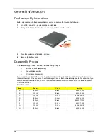
Remove the battery pack.
Disassembly Process
The disassembly process is divided into the following stages:
•
External module disassembly
•
Main unit disassembly
•
LCD module disassembly
The flowcharts provided in the succeeding disassembly sections illustrate the entire disassembly sequence.
Observe the order of the sequence to avoid damage to any of the hardware components. For example, if you
want to remove the main board, you must first remove the keyboard, then disassemble the inside assembly
frame in that order.
Main Screw List
Item
Screw
Color
Part No.
A
M2.5 x L6
Black
86.00E33.736
B
M2 x L4
Black
86.00A02.140
C
M2 x L4
Silver
86.9A552.4R0
D
M2.5 x L5
Silver
86.00E74.335
E
M2.5 x L5
Black
86.00F87.735
F
M2 x L3
Silver
86.00C07.220
G
M3 x L4
Silver
86.9A544.4R0
H
M2.5 x L8
Black
86.00E34.738
Summary of Contents for 5520 5929 - TravelMate - Turion 64 X2 2 GHz
Page 6: ...VI ...
Page 10: ...X Table of Contents ...
Page 65: ...Chapter 2 55 ...
Page 66: ...56 Chapter 2 ...
Page 112: ...102 Chapter 3 ...
Page 126: ...116 Chapter 4 F5h Boot to Mini DOS F6h Clear Huge Segment F7h Boot to Full DOS Code Beeps ...
Page 138: ...128 Chapter 5 ...
Page 172: ...Appendix A 162 ...
Page 178: ...168 Appendix C ...

