Chapter 4
161
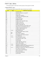
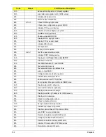
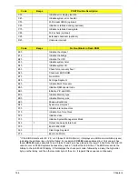
POST Codes Tables
These tables describe the POST codes, functions, phases, and components for the POST.
Chipset POST Codes
The following table details the chipset POST codes and functions used in the POST.
Code
Beeps
POST Routine Description
02h
Verify Real Mode
03h
Disable Non-Maskable Interrupt (NMI)
04h
Get CPU type
06h
Initialize system hardware
08h
Initialize chipset with initial POST values
09h
Set IN POST flag
0Ah
Initialize CPU registers
0Bh
Enable CPU cache
0Ch
Initialize caches to initial POST values
0Eh
Initialize I/O component
0Fh
Initialize the local bus IDE
10h
Initialize Power Management
11h
Load alternate registers with initial POST values
12h
Restore CPU control word during warm boot
13h
Initialize PCI Bus Mastering devices
14h
Initialize keyboard controller
16h
1-2-2-3
BIOS ROM checksum
17h
Initialize cache before memory autosize
18h
8254
timer initialization
1Ah
8237
DMA controller initialization
1Ch
Reset Programmable Interrupt Controller
20h
1-3-1-1
Test DRAM refresh
22h
1-3-1-3
Test 8742 Keyboard Controller
24h
Set ES segment register to 4 GB
26h
Enable A20 line
28h
Autosize DRAM
29h
Initialize POST Memory Manager
2Ah
Clear 512 KB base RAM
2Ch
1-3-4-1
RAM failure on address line xxxx*
2Eh
1-3-4-3
RAM failure on data bits xxxx* of low byte of memory bus
2Fh
Enable cache before system BIOS shadow
30h
1-4-1-1
RAM failure on data bits xxxx* of high byte of memory bus
32h
Test CPU bus-clock frequency
33h
Initialize Phoenix Dispatch Manager
36h
Warm start shut down
38h
Shadow system BIOS ROM
3Ah
Autosize cache
Summary of Contents for 5530 5634 - TravelMate - Athlon X2 2.1 GHz
Page 6: ...VI ...
Page 14: ...4 Chapter 1 System Block Diagram ...
Page 36: ...26 Chapter 1 ...
Page 54: ...44 Chapter 2 ...
Page 56: ...46 Chapter 2 ...
Page 64: ...54 Chapter 3 6 Remove the HDD cover as shown 7 Remove the WLAN cover as shown ...
Page 85: ...Chapter 3 75 6 Turn the upper cover over The upper cover appears as follows ...
Page 106: ...96 Chapter 3 7 Lift the Thermal Module clear of the Mainboard ...
Page 112: ...102 Chapter 3 6 Disconnect the left and right Inverter board cables as shown ...
Page 126: ...116 Chapter 3 3 Replace the RJ 11 cable in its housing ...
Page 137: ...Chapter 3 127 2 Replace the bracket as shown 3 Replace the single securing screw ...
Page 140: ...130 Chapter 3 2 Connect the seven cables on the mainboard as shown B C D E F G A ...
Page 152: ...142 Chapter 3 ...
Page 180: ...170 Chapter 5 ...
Page 196: ...Appendix A 186 ...
Page 202: ...192 Appendix B ...
Page 204: ...194 Appendix C ...
Page 207: ...197 Windows 2000 Environment Test 188 Wireless Function Failure 156 WLAN Board 56 ...
Page 208: ...198 ...

