Chapter 1
23
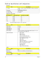
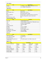
Video Memory
USB Interface
System Board Major Chips
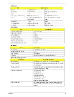
Keyboard
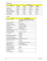
Battery 6 Cell
Item
Specification
Chipset
RS780MN for UMA, M82ME-XT/M86ME for Discrete
Memory size
Up to 512MB for Discrete SKU
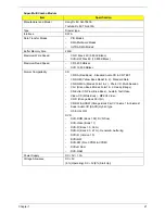
Item
Specification
Chipset
AMD SB700
USB Compliancy Level
Support USB 1.1 and 2.0
OHCI
5 OHCI and 2 EHCI controller
Number of USB port
Chipset support 12 port(4 external port on the system)
Location
2 ports on the right side, 2 ports on the left side
Serial port function control
N/A
Item
Controller
Core logic
AMD SB700
VGA
AMD RS780MN for UMA, M82ME-XT/M86ME for Discrete
LAN
Broadcom BCM5764MKMLG
USB 2.0
SB700 embedded
Super I/O controller
N/A
MODEM
Foxconn T60M955
Bluetooth
Broadcom 2045
Wireless 802.11 b+g
Foxconn XB63 and 4312
PCMCIA/ 5 in 1 Card Reader
JMicron JMB385
Audio Codec
Realtek ALC888S
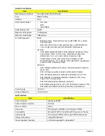
Item
Specification
Keyboard controller
LPC interface
Total number of keypads
88-/89-/93-key
Windows logo key
Yes
Internal & external keyboard work
simultaneously
Plug USB keyboard to the USB port directly: Yes
Item
Specification
Vendor & model name
Sanyo &
AS07B31
Sony &
AS07B41
Panasonic &
AS07B51
Simplo &
AS07B71
Battery Type
Li-ion
Li-ion
Li-ion
Li-ion
Pack capacity
4500mAh
4500mAh
4500mAh
4500mAh
Number of battery cell
6cell
6cell
6cell
6cell
Package configuration
3S2P
3S2P
3S2P
3S2P
Normal voltage
10.8V
11.1V
11.1V
11.1V
Charge voltage
12.6V
12.6V
12.6V
12.6V
Summary of Contents for 5530 5634 - TravelMate - Athlon X2 2.1 GHz
Page 6: ...VI ...
Page 14: ...4 Chapter 1 System Block Diagram ...
Page 36: ...26 Chapter 1 ...
Page 54: ...44 Chapter 2 ...
Page 56: ...46 Chapter 2 ...
Page 64: ...54 Chapter 3 6 Remove the HDD cover as shown 7 Remove the WLAN cover as shown ...
Page 85: ...Chapter 3 75 6 Turn the upper cover over The upper cover appears as follows ...
Page 106: ...96 Chapter 3 7 Lift the Thermal Module clear of the Mainboard ...
Page 112: ...102 Chapter 3 6 Disconnect the left and right Inverter board cables as shown ...
Page 126: ...116 Chapter 3 3 Replace the RJ 11 cable in its housing ...
Page 137: ...Chapter 3 127 2 Replace the bracket as shown 3 Replace the single securing screw ...
Page 140: ...130 Chapter 3 2 Connect the seven cables on the mainboard as shown B C D E F G A ...
Page 152: ...142 Chapter 3 ...
Page 180: ...170 Chapter 5 ...
Page 196: ...Appendix A 186 ...
Page 202: ...192 Appendix B ...
Page 204: ...194 Appendix C ...
Page 207: ...197 Windows 2000 Environment Test 188 Wireless Function Failure 156 WLAN Board 56 ...
Page 208: ...198 ...


