24
Chapter 1
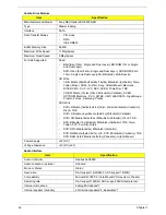
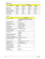
Battery 8 Cell
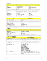
LCD 15.4”
Item
Specification
Vendor & model name
Sanyo &
AS07B32
Sony &
AS07B42
Panasonic &
AS07B52
Simplo &
AS07B72
Battery Type
Li-ion
Li-ion
Li-ion
Li-ion
Pack capacity
4800mAh
4800mAh
4800mAh
4800mAh
Number of battery cell
8cell
8cell
8cell
8cell
Package configuration
4S2P
4S2P
4S2P
4S2P
Normal voltage
14.8V
14.8V
14.8V
14.8V
Charge voltage
16.8V
16.8V
16.8V
16.8V
Item
Specification
Vendor/model name
Chimei N154I3-L03, Samsung LTN154AT01-
A01, AUO B154EW08 V1(HW 3A), LG.Philips
LP154WX4
Screen Diagonal (mm)
391
Active Area (mm)
331.2 X 207.0
Display resolution (pixels)
1280x (RGB) x 800
Pixel Pitch
0.2588 (H) x 0.2588 (V)
Pixel Arrangement
RGB vertical stripe
Display Mode
Normally white
Typical White Luminance (cd/m
2
)
also called Brightness
220 cd/m2 (Typ.5 point)
Luminance Uniformity
1.25 max. (5 points)
Contrast Ratio
300 Min
400 typical
Response Time (Optical Rise
Time/Fall Time) msec
Rising: 6
Falling: 2
Nominal Input Voltage VDD
+3.3 typ.
Typical Power Consumption (watt)
6.0 max.(without inverter)
Weight (without inverter)
500 typ.
525 max.
Physical Size (mm)
344.0 typ. x 222.0 typ. x 6.1 max.
Electrical Interface
1 channel LVDS
Support Color
262K colors (RGB 6-bit)
Viewing Angle (degree)
Horizontal: Right/Left
Vertical: Upper/Lower
40/40
15/30
Temperature Range (°C)
Operating
Storage (shipping)
0 to +50
-20 to +60
Summary of Contents for 5530 5634 - TravelMate - Athlon X2 2.1 GHz
Page 6: ...VI ...
Page 14: ...4 Chapter 1 System Block Diagram ...
Page 36: ...26 Chapter 1 ...
Page 54: ...44 Chapter 2 ...
Page 56: ...46 Chapter 2 ...
Page 64: ...54 Chapter 3 6 Remove the HDD cover as shown 7 Remove the WLAN cover as shown ...
Page 85: ...Chapter 3 75 6 Turn the upper cover over The upper cover appears as follows ...
Page 106: ...96 Chapter 3 7 Lift the Thermal Module clear of the Mainboard ...
Page 112: ...102 Chapter 3 6 Disconnect the left and right Inverter board cables as shown ...
Page 126: ...116 Chapter 3 3 Replace the RJ 11 cable in its housing ...
Page 137: ...Chapter 3 127 2 Replace the bracket as shown 3 Replace the single securing screw ...
Page 140: ...130 Chapter 3 2 Connect the seven cables on the mainboard as shown B C D E F G A ...
Page 152: ...142 Chapter 3 ...
Page 180: ...170 Chapter 5 ...
Page 196: ...Appendix A 186 ...
Page 202: ...192 Appendix B ...
Page 204: ...194 Appendix C ...
Page 207: ...197 Windows 2000 Environment Test 188 Wireless Function Failure 156 WLAN Board 56 ...
Page 208: ...198 ...

