Service and Maintenance
5-39
USB Board Installation
1.
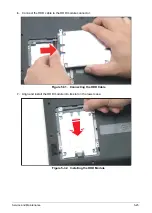
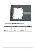
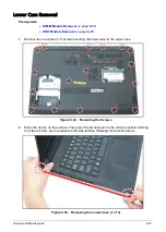
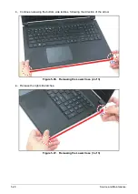
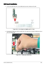
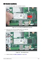
Connect the USB board FFC to the USB board connector and secure the latch.
Figure 5-54. Connecting the USB Board FFC (1 of 2)
2.
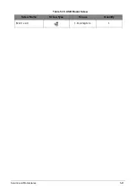
By aligning the USB board with the guide pins on the upper case, install the USB board onto its
slot on the upper case.
Figure 5-55. Installing the USB Board
Summary of Contents for A315-53G
Page 1: ...A315 53 A315 53G S E R V I C E G U I D E ...
Page 23: ...Hardware Specifications and Configurations 1 16 Figure 1 8 System Block Diagram Discrete ...
Page 224: ...5 84 Service and Maintenance Figure 5 129 Disconnecting the Cables UMA C A F D B E G H I ...
Page 230: ...5 90 Service and Maintenance Figure 5 139 Connecting the Cables UMA C A F D B E G H I ...
Page 301: ...CHAPTER 8 Online Support Information Online Support Information 8 2 Introduction 8 2 ...
Page 303: ......

