System Utilities
2-18
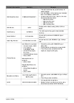
NOTE:
•
Wired connection will display
Network Boot-IPV4
and
Network Boot-IPV6
as two
separate network boot devices.
•
After Windows 10 OS is installed, a
Windows Boot Manager
will be generated and
displayed on top of the boot device priority.
•
Non-physical boot devices can be deleted in the Boot Priority Order List, this includes
A
trusted boot entry
and
Windows Boot Manager
.
•
If two (2) HDD is configured as RAID, only HDD0 is presented.
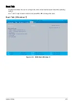
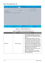
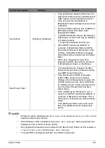
Secure Boot
[Enabled] / [Disabled]
• If the default Boot Mode is [UEFI] then the
default Secure Boot status is [Enabled] and
CSM module can’t be loaded during boot.
• If the user sets the Secure Boot to
[Disabled], firmware will bypass secure boot
verification.
• The Secure Boot status is only available on
[UEFI] Boot Mode but hidden under
[Legacy] Boot Mode.
• In [UEFI] Boot Mode, Secure Boot status is
default gray out and could only be modified
by following actions:
1. Supervisor password had been set.
• When BIOS “Load Setup Defaults” is
executed, if default Boot Mode is [UEFI],
Secure Boot will reset to [Enabled], on the
contrary, if default Boot Mode is [Legacy],
Secure Boot will be disable and hid in Boot
Menu.
• When user change Boot mode from
[Legacy] to [UEFI], Secure Boot will be set
to [Enabled] and shown on Boot Menu.
Boot Priority Order
• If the Boot Mode has changed, the Boot
Priority Order will not be refreshed until the
next BIOS Setup Utility entry.
• If the Boot Mode is [UEFI] or [Legacy]
(UEFI+CSM) and you have enabled
Windows To GO Startup Options under OS,
an USB class boot entry name “USB Entry
for Windows To GO” will be inserted into the
top of the Boot Priority Order and Boot
Option Menu.
• If the “USB Entry for Windows To Go” is
present, and BIOS “Load Setup Defaults” is
executed, “USB Entry for Windows To Go”
will be set to 1st Boot Device in Boot Priority
Order.
• If the eMMc plus HDD exists at the same
time, then eMMc will be the default boot
device.
Product Information
Example
Remark
Summary of Contents for A315-53G
Page 1: ...A315 53 A315 53G S E R V I C E G U I D E ...
Page 23: ...Hardware Specifications and Configurations 1 16 Figure 1 8 System Block Diagram Discrete ...
Page 224: ...5 84 Service and Maintenance Figure 5 129 Disconnecting the Cables UMA C A F D B E G H I ...
Page 230: ...5 90 Service and Maintenance Figure 5 139 Connecting the Cables UMA C A F D B E G H I ...
Page 301: ...CHAPTER 8 Online Support Information Online Support Information 8 2 Introduction 8 2 ...
Page 303: ......

