2-25
System Utilities
IMPORTANT:
•
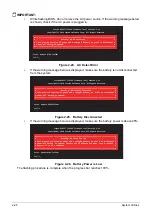
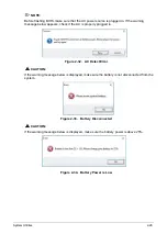
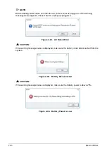
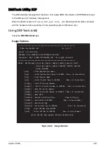
While flashing BIOS, do not remove the AC power source. If the warning message below
is shown, check if the AC power is plugged in.
Figure 2-24. AC Detect Error
•
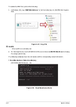
If the warning message below is displayed, make sure the battery is not disconnected
from the system.
Figure 2-25. Battery Disconnected
•
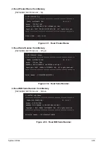
If the warning message below is displayed, make sure the battery power is above 25%.
Figure 2-26. Battery Power is Low
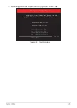
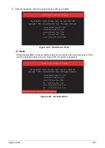
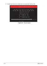
The flashing procedure is complete when the progress bar reaches 100%.
_______________________
Please do not remove the AC power!
Insyde H2OFFT (Flash Firmware Tool) Version 1.3u
Copyright(C) 2016 Insyde Software Corp. All Rights Reserved.
!
!
Error: Update BIOS Failed!
Fs1:\>_
#=============================================================================#
# Warning: NO AC Connected
#
# This process requires AC power and a charged battery to avoid an accidental #
# power-off during an update. #
#=============================================================================#
_______________________
Please do not remove the AC power!
Insyde H2OFFT (Flash Firmware Tool) Version 1.3u
Copyright(C) 2016 Insyde Software Corp. All Rights Reserved.
!
!
Error: Update BIOS Failed!
Fs1:\>_
#=============================================================================#
# Warning: NO Battery Connected
#
# This process requires AC power and a charged battery to avoid an accidental #
# power-off during an update. #
#=============================================================================#
_______________________
Please do not remove the AC power!
Insyde H2OFFT (Flash Firmware Tool) Version 1.3u
Copyright(C) 2016 Insyde Software Corp. All Rights Reserved.
!
!
Error: Update BIOS Failed!
Fs1:\>_
#=============================================================================#
# Warning: Battery Too Low
#
# This process requires AC power and a charged battery to avoid an accidental #
# power-off during an update. Connect the AC adapter and make sure a charged #
# battery is in the computer. #
#=============================================================================#
Summary of Contents for A315-53G
Page 1: ...A315 53 A315 53G S E R V I C E G U I D E ...
Page 23: ...Hardware Specifications and Configurations 1 16 Figure 1 8 System Block Diagram Discrete ...
Page 224: ...5 84 Service and Maintenance Figure 5 129 Disconnecting the Cables UMA C A F D B E G H I ...
Page 230: ...5 90 Service and Maintenance Figure 5 139 Connecting the Cables UMA C A F D B E G H I ...
Page 301: ...CHAPTER 8 Online Support Information Online Support Information 8 2 Introduction 8 2 ...
Page 303: ......

