3-4
Jumper and Connector Locations
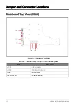
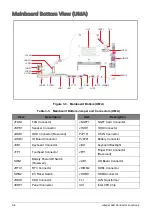
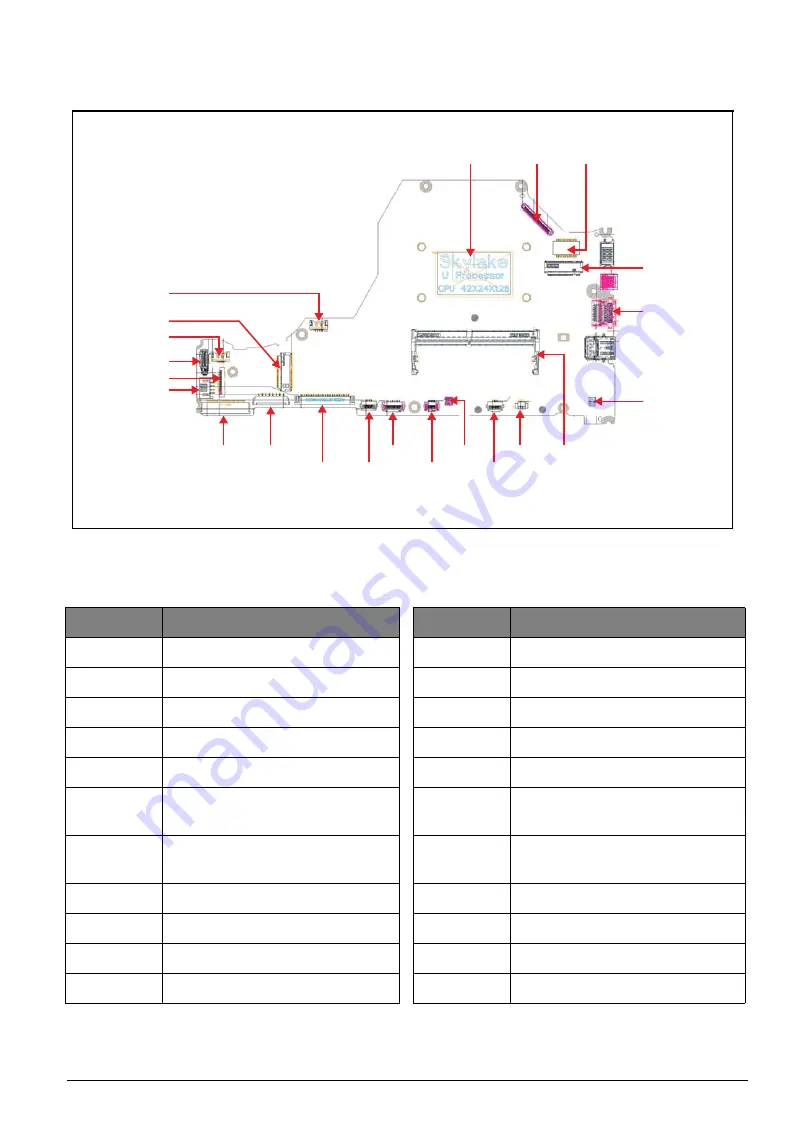
Mainboard Bottom View (UMA)
Figure 3-3. Mainboard Bottom (UMA)
Table 3-3. Mainboard Bottom Jumper and Connectors (UMA)
Item
Description
Item
Description
JFAN1
FAN Connector
JNGFF1
NGFF Card Connector
JSPK1
Speaker Connector
JHDD1
HDD Connector
JODD1
ODD Connector (Reserved)
PJP101
DC-IN Connector
JUSB3
IO Board Connector
PJP201
Battery Connector
JKB1
Keyboard Connector
JBL1
Keyboard Backlight
JTP1
Touchpad Connector
JFP1
Finger Print Connector
(Reserved)
SWG1
Battery Power Off Switch
(Reserved)
JLID1
LID Board Connector
JRTC1
RTC Connector
JDIMM2
DDR4 Connector
SWG2
EC Reset Switch
JHDMI1
HDMI Connector
JSSD1
SSD Connector
TL1
LAN Transformer
JEDP1
Panel Connector
UC1
Intel CPU Chip
SWG1
JRTC1 JDIMM2
JBL1
JKB1
JFP1
JLID1
JTP1
JUSB3
PJP201
UC1
JEDP1
TL1
JHDD1
JSPK1
JNGFF1
JFAN1
PJP101
JODD1
SWG2
JHDMI1
JSSD1
Summary of Contents for A315-53G
Page 1: ...A315 53 A315 53G S E R V I C E G U I D E ...
Page 23: ...Hardware Specifications and Configurations 1 16 Figure 1 8 System Block Diagram Discrete ...
Page 224: ...5 84 Service and Maintenance Figure 5 129 Disconnecting the Cables UMA C A F D B E G H I ...
Page 230: ...5 90 Service and Maintenance Figure 5 139 Connecting the Cables UMA C A F D B E G H I ...
Page 301: ...CHAPTER 8 Online Support Information Online Support Information 8 2 Introduction 8 2 ...
Page 303: ......

