5-34
Service and Maintenance
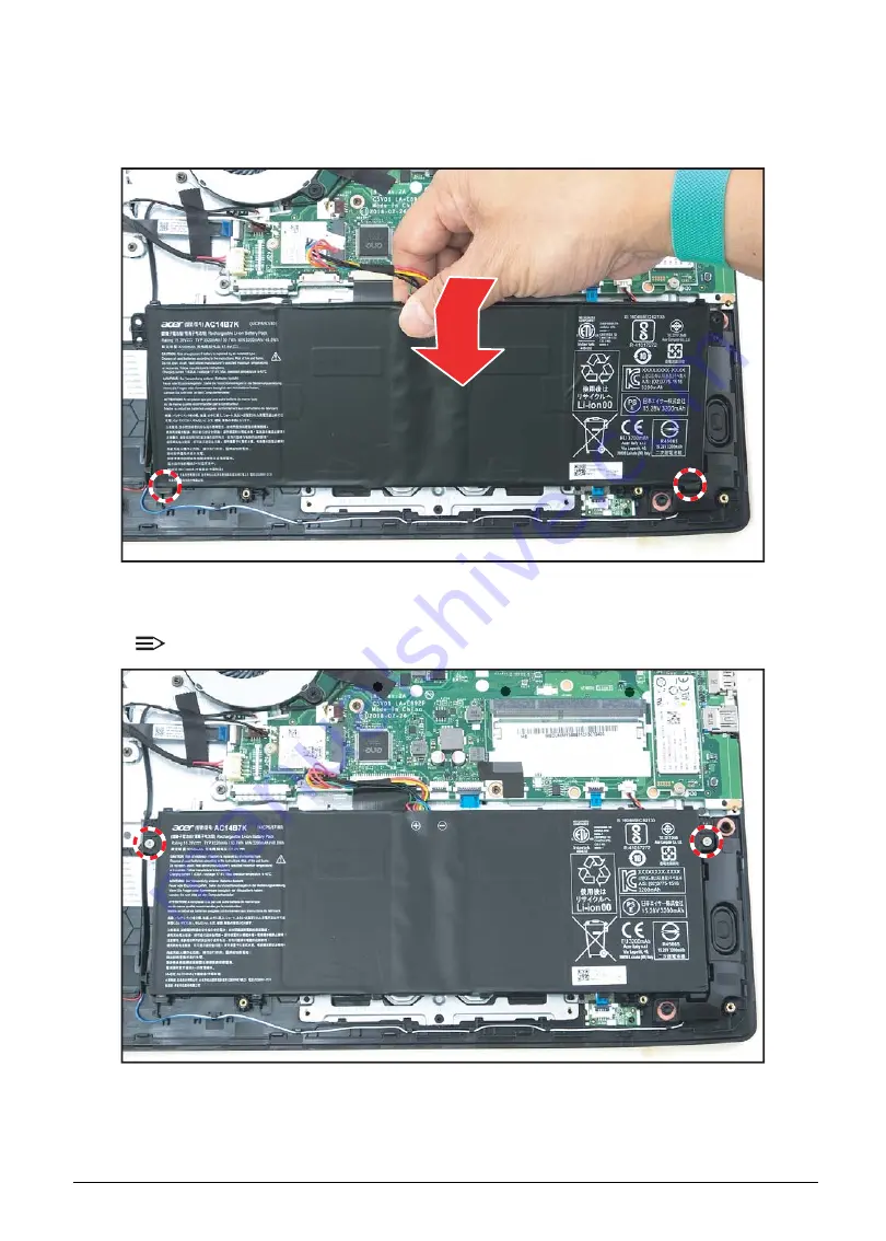
Battery Installation
1.
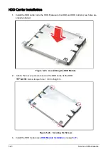
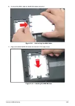
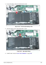
Align and slide the bottom tabs to the slots on the upper case. Then push down the battery into
its slot until it fully seated.
Figure 5-46. Installing the Battery
2.
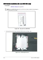
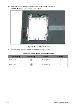
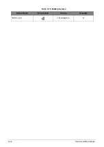
Attach the two (2) screws to secure the battery to the upper case.
NOTE:
Screw torque force = 1.8~2.2kgf.cm
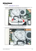
Figure 5-47. Securing the Screws
Summary of Contents for A315-53G
Page 1: ...A315 53 A315 53G S E R V I C E G U I D E ...
Page 23: ...Hardware Specifications and Configurations 1 16 Figure 1 8 System Block Diagram Discrete ...
Page 224: ...5 84 Service and Maintenance Figure 5 129 Disconnecting the Cables UMA C A F D B E G H I ...
Page 230: ...5 90 Service and Maintenance Figure 5 139 Connecting the Cables UMA C A F D B E G H I ...
Page 301: ...CHAPTER 8 Online Support Information Online Support Information 8 2 Introduction 8 2 ...
Page 303: ......

