x
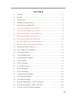
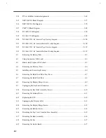
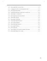
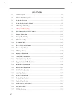
Pin Diagram ...................................................................................................2-94
Pin Description...............................................................................................2-95
Functions Description.....................................................................................2-96
Charge Function ..........................................................................2-96
Discharge Function......................................................................2-96
Safety Concerns ...........................................................................2-97
T62.061.C DC-DC Converter .........................................................................................2-98
Pin Diagram ...................................................................................................2-98
Pin Assignment ..............................................................................................2-98
Specifications .................................................................................................2-99
Control .........................................................................................................2-100
Application: .................................................................................................2-100
T62.064.C DC-AC Inverter (11.3”) ..............................................................................2-102
Electrical Specifications ...............................................................................2-102
Pin & Connector Assignment .......................................................................2-103
Top Overlay .................................................................................................2-104
Bottom Overlay ............................................................................................2-104
T62.066.C DC-AC Inverter (12.1”) ..............................................................................2-105
Electrical Specifications ...............................................................................2-105
Pin & Connector Assignment .......................................................................2-106
Top Overlay .................................................................................................2-107
Bottom Overlay ............................................................................................2-107
When to Use Setup ...........................................................................................................3-1
Entering Setup..................................................................................................................3-2
Basic System Configuration..............................................................................................3-4
Date and Time..................................................................................................3-4
Floppy Disk Drives...........................................................................................3-4
Hard Disk Drive ...............................................................................................3-4
Large Hard Disk Capacity ................................................................................3-4
Memory Test ....................................................................................................3-5
Boot Display.....................................................................................................3-5
Quiet Boot ........................................................................................................3-5
Summary of Contents for AcerNote Light 370P
Page 6: ...vi ...
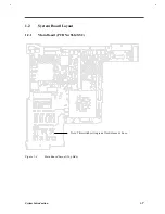
Page 26: ...1 8 Service Guide Figure 1 5 Main Board Layout Bottom Side ...
Page 49: ...System Introduction 1 31 1 5 1 3 Power Management Figure 1 14 Power Management Block Diagram ...
Page 55: ...System Introduction 1 37 1 6 System Block Diagram Figure 1 15 System Block Diagram ...
Page 64: ...Major Chips Description 2 7 2 2 5 Pin Diagram Figure 2 4 M1521 Pin Diagram ...
Page 99: ...2 42 Service Guide 2 5 3 Pin Diagram Figure 2 10 C T 65550 Pin Diagram ...
Page 117: ...2 60 Service Guide Figure 2 12 Functional block diagram CardBus Card Interface ...
Page 119: ...2 62 Service Guide Figure 2 14 PCI to CardBus terminal assignments ...
Page 135: ...2 78 Service Guide 2 7 3 Pin Diagram Figure 2 16 NS87336VJG Pin Diagram ...
Page 145: ...2 88 Service Guide 2 8 2 Pin Diagram Figure 2 17 YMF715 Block Diagram ...
Page 185: ...Disassembly and Unit Replacement 4 5 Figure 4 3 Disassembly Sequence Flowchart ...
Page 209: ...B 2 Service Guide ...
Page 210: ...Exploded View Diagram B 3 ...


