xi
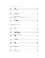
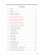
System Security................................................................................................................ 3-6
Floppy Disk Drive Control ............................................................................... 3-6
Hard Disk Drive Control .................................................................................. 3-6
System Boot Drive Control............................................................................... 3-7
CD-ROM Bootable........................................................................................... 3-7
Serial Port 1 Base Address ............................................................................... 3-8
Parallel Port Base Address ............................................................................... 3-8
Parallel Port Operation Mode ........................................................................... 3-8
Passwords ........................................................................................................ 3-9
CardBus Support............................................................................................ 3-10
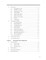
Power Management Settings .......................................................................................... 3-11
Power Management Mode .............................................................................. 3-11
Display Standby Timer................................................................................... 3-11
Hard Disk Standby Timer............................................................................... 3-11
System Sleep Timer ....................................................................................... 3-12
System Sleep Mode ........................................................................................ 3-12
System Resume Timer Mode .......................................................................... 3-12
System Resume Date and Time ...................................................................... 3-12
Modem Ring Resume On Indicator ................................................................ 3-12
Battery-low Warning Beep ............................................................................. 3-13
Sleep Upon Battery-low.................................................................................. 3-13
System Information Reference........................................................................................ 3-14
Load Setup Default Settings ........................................................................................... 3-16
Disassembly and Unit Replacement
General Information......................................................................................................... 4-2
Before You Begin............................................................................................. 4-2
Connector Types .............................................................................................. 4-3
Disassembly Sequence...................................................................................... 4-4
Replacing Memory ........................................................................................................... 4-6
Removing the Hard Disk Drive ........................................................................................ 4-7
Removing the Keyboard ................................................................................................... 4-9
Summary of Contents for AcerNote Light 370P
Page 6: ...vi ...
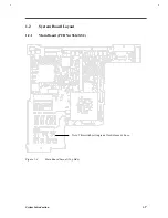
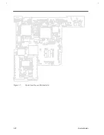
Page 26: ...1 8 Service Guide Figure 1 5 Main Board Layout Bottom Side ...
Page 49: ...System Introduction 1 31 1 5 1 3 Power Management Figure 1 14 Power Management Block Diagram ...
Page 55: ...System Introduction 1 37 1 6 System Block Diagram Figure 1 15 System Block Diagram ...
Page 64: ...Major Chips Description 2 7 2 2 5 Pin Diagram Figure 2 4 M1521 Pin Diagram ...
Page 99: ...2 42 Service Guide 2 5 3 Pin Diagram Figure 2 10 C T 65550 Pin Diagram ...
Page 117: ...2 60 Service Guide Figure 2 12 Functional block diagram CardBus Card Interface ...
Page 119: ...2 62 Service Guide Figure 2 14 PCI to CardBus terminal assignments ...
Page 135: ...2 78 Service Guide 2 7 3 Pin Diagram Figure 2 16 NS87336VJG Pin Diagram ...
Page 145: ...2 88 Service Guide 2 8 2 Pin Diagram Figure 2 17 YMF715 Block Diagram ...
Page 185: ...Disassembly and Unit Replacement 4 5 Figure 4 3 Disassembly Sequence Flowchart ...
Page 209: ...B 2 Service Guide ...
Page 210: ...Exploded View Diagram B 3 ...


