2-54
Service Guide
Table 2-10
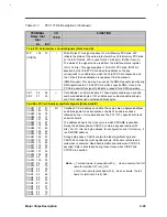
C&T 65550 Pin Descriptions (continued)
Pin#
Pin Name
Type
Description
Power / Ground and Standby Control (continued)
66
63
89
DCC
DGND
DGND
VCC
GND
GND
Power / Ground (Bus Interface) 5V
±
10% or 3.3V
±
0.3V.
158
161
142
139
108
105
MVCCA
MGNDA
MVCCB
MGNDB
MVCCC
MGNDC
Power / Ground (Bus Interface) 5V
±
10% or 3.3V
±
0.3V.
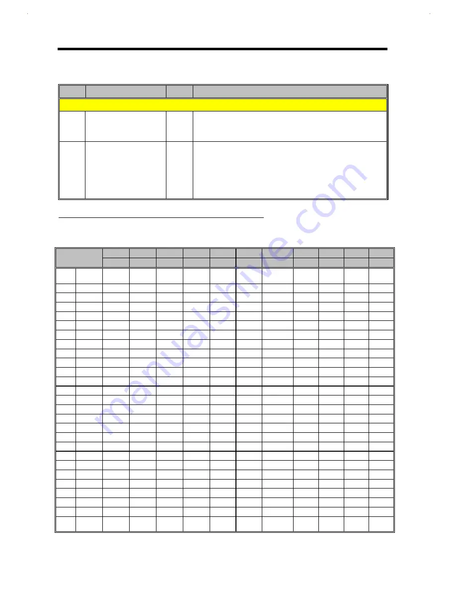
FLAT PANEL DISPLAY INTERFACE (CONFIGURATION BY PANEL TYPES)
Table 2-11
Flat Panel Display Interface Configurations
Mono
Mono
Mono
Color
Color
Color
Color STN
Color
Color
Color
Color
65550
SS
DD
DD
TFT
TFT
TFT HR
STN SS
STN SS
STN DD
STN DD
STN DD
Pin#
Pin
Name
8-bit
8-bit
16-bit
9/12/16
bit
18/24 bit
18/24 bit
8-bit
(X4bP)
16-bit
(4bP)
8-bit
(4bP)
16-bit
(4bP)
24 bit
71
P0
-
UD3
UD7
B0
B0
B00
R1
R1
UR1
UR0
UR0
72
P1
-
UD2
UD6
B1
B1
B01
B1
G1
UG1
UG0
UG0
73
P2
-
UD1
UD5
B2
B2
B02
G2
B1
UB1
UB0
UB0
74
P3
-
UD0
UD4
B3
B3
B03
R3
R2
UR2
UR1
LR0
75
P4
-
LD3
UD3
B4
B4
B10
B3
G2
LR1
LR0
LG0
76
P5
-
LD2
UD2
G0
B5
B11
G4
B2
LG1
LG0
LB0
78
P6
-
LD1
UD1
G1
B6
B12
R5
R3
LB1
LB0
UR1
79
P7
-
LD0
UD0
G2
B7
B13
B5
G3
LR2
LR1
UG1
81
P8
P0
-
LD7
G3
G0
G00
SHFCLKU
B3
-
UG1
UB1
82
P9
P1
-
LD6
G4
G1
G01
-
R4
-
UB1
LR1
83
P10
P2
-
LD5
G5
G2
G02
-
G4
-
UR2
LG1
84
P11
P3
-
LD4
R0
G3
G03
-
B4
-
UG2
LB1
85
P12
P4
-
LD3
R1
G4
G10
-
R5
-
LG1
UR2
86
P13
P5
-
LD2
R2
G5
G11
-
G5
-
LB1
UG2
87
P14
P6
-
LD1
R3
G6
G12
-
B5
-
LR2
UB2
88
P15
P7
-
LD0
R4
G7
G13
-
R6
-
LG2
LR2
90
P16
-
-
-
-
R0
R00
-
-
-
-
LG2
91
P17
-
-
-
-
R1
R01
-
-
-
-
LB2
92
P18
-
-
-
-
R2
R02
-
-
-
-
UR3
93
P19
-
-
-
-
R3
R03
-
-
-
-
UG3
94
P20
-
-
-
-
R4
R10
-
-
-
-
UB3
95
P21
-
-
-
-
R5
R11
-
-
-
-
LR3
96
P22
-
-
-
-
R6
R12
-
-
-
-
LG3
97
P23
-
-
-
-
R7
R13
-
-
-
-
LB3
70
SHFCLK
SHFCLK
SHFCLK
SHFCLK
SHFCLK
SHFCLK
SHFCLK
SHFCLK
SHFCLK
SHFCLK
SHFCLK
SHFCLK
Pixels /
Clock:
8
8
16
1
1
2
2-2/3
5-1/3
2-2/3
5-1/3
8
Summary of Contents for AcerNote Light 370P
Page 6: ...vi ...
Page 26: ...1 8 Service Guide Figure 1 5 Main Board Layout Bottom Side ...
Page 49: ...System Introduction 1 31 1 5 1 3 Power Management Figure 1 14 Power Management Block Diagram ...
Page 55: ...System Introduction 1 37 1 6 System Block Diagram Figure 1 15 System Block Diagram ...
Page 64: ...Major Chips Description 2 7 2 2 5 Pin Diagram Figure 2 4 M1521 Pin Diagram ...
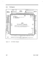
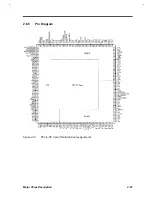
Page 99: ...2 42 Service Guide 2 5 3 Pin Diagram Figure 2 10 C T 65550 Pin Diagram ...
Page 117: ...2 60 Service Guide Figure 2 12 Functional block diagram CardBus Card Interface ...
Page 119: ...2 62 Service Guide Figure 2 14 PCI to CardBus terminal assignments ...
Page 135: ...2 78 Service Guide 2 7 3 Pin Diagram Figure 2 16 NS87336VJG Pin Diagram ...
Page 145: ...2 88 Service Guide 2 8 2 Pin Diagram Figure 2 17 YMF715 Block Diagram ...
Page 185: ...Disassembly and Unit Replacement 4 5 Figure 4 3 Disassembly Sequence Flowchart ...
Page 209: ...B 2 Service Guide ...
Page 210: ...Exploded View Diagram B 3 ...

